HW-SPAR3E-SK-UK-G Xilinx Inc, HW-SPAR3E-SK-UK-G Datasheet - Page 99
HW-SPAR3E-SK-UK-G
Manufacturer Part Number
HW-SPAR3E-SK-UK-G
Description
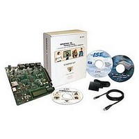
KIT STARTER SPARTAN-3E
Manufacturer
Xilinx Inc
Specifications of HW-SPAR3E-SK-UK-G
Tool / Board Applications
General Purpose MCU, MPU, DSP, DSC
Development Tool Type
Hardware / Software - Starter Kit
Mcu Supported Families
Spartan-3E
Lead Free Status / RoHS Status
Lead free / RoHS Compliant
Other names
HW-SPAR3E-SK-US-UK-G
HW-SPAR3E-SK-US-UK-G
HW-SPAR3E-SK-US-UK-G
Available stocks
Company
Part Number
Manufacturer
Quantity
Price


Spartan-3E FPGA Starter Kit Board User Guide
UG230 (v1.2) January 20, 2011
R
Insert Jumper on JP8 and Hold PROG_B Low
Table 12-2: Cable Connections to J12 Header
The JTAG parallel programming cable directly accesses the SPI Flash pins. To avoid signal
contention with the FPGA, ensure that the connecting FPGA pins are high-impedance.
Force the FPGA’s PROG_B pin Low by installing a jumper on JP8, next to the PROG push
button, as shown in
surrounding landmarks.
Re-apply power to the Spartan-3E Starter Kit board and program the SPI Flash.
a) No Jumper: FPGA Operational (default)
J12 Header Label
JTAG3 Cable Label
Flying Leads Label
Figure 12-16: Installing the JP8 Jumper Holds the FPGA in Configuration State
Cable and Labels
Figure 12-15: Attaching a JTAG Parallel Programming Cable to the Board
a) JTAG3 Parallel Connector
PROG
GND
JP8
Figure
PROG
www.xilinx.com
12-16. See
PROG
TMS/
TMS
SEL
Figure 12-3, page 92
TDI/
DIN
SDI
TDI
b) Jumper Installed: FPGA Held in
Configuration State, I/Os in High Impedance
b) Parallel Cable III or Parallel Cable IV
DONE
TDO/
SDO
TDO
with Flying Leads
Connections
PROG
GND
to locate jumper JP8 and
TCK/
CCLK
JP8
TCK
SCK
Configuring from SPI Flash
PROG
GND/
GND
GND
GND
UG230_c15_14_030206
UG230_c15_15_030206
VREF/
VREF
VCC
VCC
99
Related parts for HW-SPAR3E-SK-UK-G
Image
Part Number
Description
Manufacturer
Datasheet
Request
R

Part Number:
Description:
KIT STARTER SPARTAN-3E
Manufacturer:
Xilinx Inc
Datasheet:
Part Number:
Description:
KIT STARTER SPARTAN-3E
Manufacturer:
Xilinx Inc
Datasheet:
Part Number:
Description:
KIT DEV SPARTAN3E DISPLAY
Manufacturer:
Xilinx Inc
Part Number:
Description:
KIT DEV SPARTAN3E DISPLAY
Manufacturer:
Xilinx Inc
Datasheet:

Part Number:
Description:
IC CPLD .8K 36MCELL 44-VQFP
Manufacturer:
Xilinx Inc
Datasheet:

Part Number:
Description:
IC CPLD 72MCRCELL 10NS 44VQFP
Manufacturer:
Xilinx Inc
Datasheet:

Part Number:
Description:
IC CPLD 1.6K 72MCELL 64-VQFP
Manufacturer:
Xilinx Inc
Datasheet:

Part Number:
Description:
IC CR-II CPLD 64MCELL 44-VQFP
Manufacturer:
Xilinx Inc
Datasheet:

Part Number:
Description:
IC CPLD 1.6K 72MCELL 100-TQFP
Manufacturer:
Xilinx Inc
Datasheet:

Part Number:
Description:
IC CR-II CPLD 64MCELL 56-BGA
Manufacturer:
Xilinx Inc
Datasheet:

Part Number:
Description:
IC CPLD 72MCRCELL 7.5NS 44VQFP
Manufacturer:
Xilinx Inc
Datasheet:
Part Number:
Description:
IC CR-II CPLD 64MCELL 100-VQFP
Manufacturer:
Xilinx Inc
Datasheet: