C8051F700DK Silicon Laboratories Inc, C8051F700DK Datasheet - Page 280
C8051F700DK
Manufacturer Part Number
C8051F700DK
Description
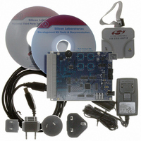
DEV KIT FOR C8051F700
Manufacturer
Silicon Laboratories Inc
Type
MCUr
Datasheets
1.C8051F700-TB.pdf
(1 pages)
2.C8051F700-TB.pdf
(306 pages)
3.C8051F700-TB.pdf
(18 pages)
Specifications of C8051F700DK
Contents
Board, Cables, CD, Debugger, Power Supply
Processor To Be Evaluated
C8051F7x
Processor Series
C8051F7xx
Interface Type
USB
Operating Supply Voltage
3.3 V
Lead Free Status / RoHS Status
Lead free / RoHS Compliant
For Use With/related Products
C8051F7xx
Lead Free Status / Rohs Status
Lead free / RoHS Compliant
Other names
336-1635


C8051F70x/71x
33.3.3. Comparator 0 Capture Mode
The capture mode in Timer 3 allows Comparator 0 rising edges to be captured with the timer clocking from
the system clock or the system clock divided by 12. Timer 3 capture mode is enabled by setting TF3CEN
to 1 and T3SPLIT to 0.
When capture mode is enabled, a capture event will be generated on every Comparator 0 rising edge.
When the capture event occurs, the contents of Timer 3 (TMR3H:TMR3L) are loaded into the Timer 3
reload registers (TMR3RLH:TMR3RLL) and the TF3H flag is set (triggering an interrupt if Timer 3 inter-
rupts are enabled). By recording the difference between two successive timer capture values, the
Comparator 0 period can be determined with respect to the Timer 3 clock. The Timer 3 clock should be
much faster than the capture clock to achieve an accurate reading.
This mode allows software to determine the time between consecutive Comparator 0 rising edges, which
can be used for detecting changes in the capacitance of a capacitive switch, or measuring the frequency of
a low-level analog signal.
280
External Clock / 8
Comparator 0
SYSCLK / 12
SYSCLK
Output
T3XCLK
0
1
Figure 33.9. Timer 3 Capture Mode Block Diagram
T
M
H
3
M
T
3
L
0
1
CKCON
M
H
T
2
T
M
2
L
M
T
1
TF3CEN
M
T
0
S
C
A
1
TR3
S
C
A
0
Capture
Rev. 1.0
TCLK
TMR3RLL TMR3RLH
TMR3L
TMR3H
TF3CEN
T3SPLIT
TF3LEN
T3XCLK
TF3H
TF3L
TR3
Interrupt
Related parts for C8051F700DK
Image
Part Number
Description
Manufacturer
Datasheet
Request
R

Part Number:
Description:
SMD/C°/SINGLE-ENDED OUTPUT SILICON OSCILLATOR
Manufacturer:
Silicon Laboratories Inc
Part Number:
Description:
Manufacturer:
Silicon Laboratories Inc
Datasheet:
Part Number:
Description:
N/A N/A/SI4010 AES KEYFOB DEMO WITH LCD RX
Manufacturer:
Silicon Laboratories Inc
Datasheet:
Part Number:
Description:
N/A N/A/SI4010 SIMPLIFIED KEY FOB DEMO WITH LED RX
Manufacturer:
Silicon Laboratories Inc
Datasheet:
Part Number:
Description:
N/A/-40 TO 85 OC/EZLINK MODULE; F930/4432 HIGH BAND (REV E/B1)
Manufacturer:
Silicon Laboratories Inc
Part Number:
Description:
EZLink Module; F930/4432 Low Band (rev e/B1)
Manufacturer:
Silicon Laboratories Inc
Part Number:
Description:
I°/4460 10 DBM RADIO TEST CARD 434 MHZ
Manufacturer:
Silicon Laboratories Inc
Part Number:
Description:
I°/4461 14 DBM RADIO TEST CARD 868 MHZ
Manufacturer:
Silicon Laboratories Inc
Part Number:
Description:
I°/4463 20 DBM RFSWITCH RADIO TEST CARD 460 MHZ
Manufacturer:
Silicon Laboratories Inc
Part Number:
Description:
I°/4463 20 DBM RADIO TEST CARD 868 MHZ
Manufacturer:
Silicon Laboratories Inc
Part Number:
Description:
I°/4463 27 DBM RADIO TEST CARD 868 MHZ
Manufacturer:
Silicon Laboratories Inc
Part Number:
Description:
I°/4463 SKYWORKS 30 DBM RADIO TEST CARD 915 MHZ
Manufacturer:
Silicon Laboratories Inc
Part Number:
Description:
N/A N/A/-40 TO 85 OC/4463 RFMD 30 DBM RADIO TEST CARD 915 MHZ
Manufacturer:
Silicon Laboratories Inc
Part Number:
Description:
I°/4463 20 DBM RADIO TEST CARD 169 MHZ
Manufacturer:
Silicon Laboratories Inc