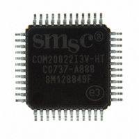
COM20022I3V-HT SMSC, COM20022I3V-HT Datasheet - Page 52

COM20022I3V-HT
Manufacturer Part Number
COM20022I3V-HT
Description
IC CTRLR ARCNET 2KX8 RAM 48-TQFP
Manufacturer
SMSC
Series
ARCNETr
Datasheet
1.COM20022I3V-HT.pdf
(82 pages)
Specifications of COM20022I3V-HT
Controller Type
ARCNET Controller
Interface
Differential
Voltage - Supply
4.5 V ~ 5.5 V
Current - Supply
65mA
Operating Temperature
-40°C ~ 85°C
Mounting Type
Surface Mount
Package / Case
48-TQFP, 48-VQFP
Lead Free Status / RoHS Status
Lead free / RoHS Compliant
Other names
638-1004
Available stocks
Company
Part Number
Manufacturer
Quantity
Price
Company:
Part Number:
COM20022I3V-HT
Manufacturer:
Standard
Quantity:
2 784
Company:
Part Number:
COM20022I3V-HT
Manufacturer:
AD
Quantity:
7 439
Company:
Part Number:
COM20022I3V-HT
Manufacturer:
Microchip Technology
Quantity:
10 000
Part Number:
COM20022I3V-HT
Manufacturer:
SMSC
Quantity:
20 000
6.7.2
Revision 09-27-07
After the first transmission is completed, the COM20022I updates the Status Register by setting the TTA
bit, which generates an interrupt. The interrupt service routine should read the Status Register. At this
point, the TTA bit will be found to be a logic "1" and the TMA (Transmit Message Acknowledge) bit will tell
the processor whether the transmission was successful. After reading the Status Register, the "Clear
Transmit Interrupt" command is issued, thus resetting the TTA bit and clearing the interrupt. Note that only
the "Clear Transmit Interrupt" command will clear the TTA bit and the interrupt. It is not necessary,
however, to clear the bit or the interrupt right away because the status of the transmit operation is double
buffered in order to retain the results of the first transmission for analysis by the processor.
information will remain in the Status Register until the "Clear Transmit Interrupt" command is issued. Note
that the interrupt will remain active until the command is issued, and the second interrupt will not occur
until the first interrupt is acknowledged. The COM20022I guarantees a minimum of 200nS (at EF=1)
interrupt inactive time interval between interrupts. The TMA bit is also double buffered to reflect whether
the appropriate transmission was a success. The TMA bit should only be considered valid after the
corresponding TTA bit has been set to a logic "1". The TMA bit never causes an interrupt.
When the token is received again, the second transmission will be automatically initiated after the first is
completed by using the stored "Enable Transmit from Page fnn" command. The operation is as if a new
"Enable Transmit from Page fnn" command has just been issued. After the first Transmit status bits are
cleared, the Status Register will again be updated with the results of the second transmission and a
second interrupt resulting from the second transmission will occur.
minimum of 200ns (at EF=1) interrupt inactive time interval before the following edge.
The Transmitter Available (TA) bit of the Interrupt Mask Register now masks only the TTA bit of the Status
Register, not the TA bit as in the non-chaining mode. Since the TTA bit is only set upon transmission of a
packet (not by RESET), and since the TTA bit may easily be reset by issuing a "Clear Transmit Interrupt"
command, there is no need to use the TA bit of the Interrupt Mask Register to mask interrupts generated
by the TTA bit of the Status Register.
In Command Chaining mode, the "Disable Transmitter" command will cancel the oldest transmission. This
permits canceling a packet destined for a node not ready to receive. If both packets should be canceled,
two "Disable Transmitter" commands should be issued.
Receive Command Chaining
Like the Transmit Command Chaining operation, the processor can issue two consecutive "Enable
Receive from Page fnn" commands.
After the first packet is received into the first specified page, the TRI bit of the Status Register will be set to
logic "1", causing an interrupt. Again, the interrupt need not be serviced immediately. Typically, the
interrupt service routine will read the Status Register. At this point, the RI bit will be found to be a logic "1".
After reading the Status Register, the "Clear Receive Interrupt" command should be issued, thus resetting
the TRI bit and clearing the interrupt. Note that only the "Clear Receive Interrupt" command will clear the
TRI bit and the interrupt. It is not necessary, however, to clear the bit or the interrupt right away because
the status of the receive operation is double buffered in order to retain the results of the first reception for
analysis by the processor, therefore the information will remain in the Status Register until the "Clear
Receive Interrupt" command is issued. Note that the interrupt will remain active until the "Clear Receive
Interrupt" command is issued, and the second interrupt will be stored until the first interrupt is
acknowledged. A minimum of 200nS (at EF=1) interrupt inactive time interval between interrupts is
guaranteed.
The second reception will occur as soon as a second packet is sent to the node, as long as the second
"Enable Receive to Page fnn" command was issued. The operation is as if a new "Enable Receive to
Page fnn" command has just been issued. After the first Receive status bits are cleared, the Status
Register will again be updated with the results of the second reception and a second interrupt resulting
from the second reception will occur.
In the COM20022I, the Receive Inhibit (RI) bit of the Interrupt Mask Register now masks only the TRI bit of
the Status Register, not the RI bit as in the non-chaining mode. Since the TRI bit is only set upon
DATASHEET
Page 52
10 Mbps ARCNET (ANSI 878.1) Controller with 2Kx8 On-Chip RAM
The COM20022I guarantees a
SMSC COM20022I
Datasheet
This


