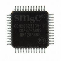
COM20022I3V-HT SMSC, COM20022I3V-HT Datasheet - Page 4

COM20022I3V-HT
Manufacturer Part Number
COM20022I3V-HT
Description
IC CTRLR ARCNET 2KX8 RAM 48-TQFP
Manufacturer
SMSC
Series
ARCNETr
Datasheet
1.COM20022I3V-HT.pdf
(82 pages)
Specifications of COM20022I3V-HT
Controller Type
ARCNET Controller
Interface
Differential
Voltage - Supply
4.5 V ~ 5.5 V
Current - Supply
65mA
Operating Temperature
-40°C ~ 85°C
Mounting Type
Surface Mount
Package / Case
48-TQFP, 48-VQFP
Lead Free Status / RoHS Status
Lead free / RoHS Compliant
Other names
638-1004
Available stocks
Company
Part Number
Manufacturer
Quantity
Price
Company:
Part Number:
COM20022I3V-HT
Manufacturer:
Standard
Quantity:
2 784
Company:
Part Number:
COM20022I3V-HT
Manufacturer:
AD
Quantity:
7 439
Company:
Part Number:
COM20022I3V-HT
Manufacturer:
Microchip Technology
Quantity:
10 000
Part Number:
COM20022I3V-HT
Manufacturer:
SMSC
Quantity:
20 000
Chapter 7
Chapter 8
Chapter 9
Chapter 10
Chapter 11
List of Figures
Figure 2.1 - COM20022I Pin Configuration ....................................................................................................................7
Figure 3.1 - COM20022I Operation..............................................................................................................................10
Figure 5.1 - Multiplexed, 8051-Like Bus Interface with RS-485 Interface .......................................................................17
Figure 5.2 - Non-Multiplexed, 6801-Like Bus Interface with RS-485 Interface ...............................................................18
Figure 5.3 - DREQ Pin First Assertion Timing for All DMA Modes ...............................................................................21
Figure 5.4 - Programmable Burst Mode DMA Transfer (Rough Timing) ......................................................................22
Figure 5.5 - Non-Burst Mode DMA Data Transfer Rough Timing.................................................................................23
Figure 5.6 - Burst Mode DMA Data Transfer Rough Timing ........................................................................................23
Figure 5.7 - High Speed CPU Bus Timing - Intel CPU Mode .......................................................................................25
Figure 5.8 - COM20022I Network Using RS-485 Differential Transceivers ....................................................................27
Figure 5.9 - Dipulse Waveform for Data of 1-1-0 ...........................................................................................................27
Figure 5.10 - Internal Block Diagram.............................................................................................................................28
Figure 6.1 - Illustration of the Effect of RTRG Bit on DMA Timing................................................................................36
Figure 6.2 - Sequential Access Operation.....................................................................................................................46
Figure 6.3 - RAM Buffer Packet Configuration .............................................................................................................49
Figure 6.4 - Command Chaining Status Register Queue .............................................................................................51
Figure 8.1 - Multiplexed Bus, 68XX-Like Control Signals; Read Cycle ........................................................................59
Figure 8.2 - Multiplexed Bus, 80XX-Like Control Signals; Read Cycle ........................................................................60
Figure 8.3 - Multiplexed Bus, 68XX-Like Control Signals Write Cycle..........................................................................61
Figure 8.4 - Multiplexed Bus, 80XX-Like Control Signals; Write Cycle.........................................................................62
Figure 8.5 - Non-Multiplexed Bus, 80XX-Like Control Signals; Read Cycle.................................................................63
Figure 8.6 - Non-Multiplexed Bus, 80XX-Like Control Signals; Read Cycle.................................................................64
Figure 8.7 - Non-Multiplexed Bus, 68XX-Like Control Signals; Read Cycle.................................................................65
Figure 8.8 - Non-Multiplexed Bus, 68XX-Like Control Signals; Read Cycle.................................................................66
Figure 8.9 - Non-Multiplexed Bus, 80XX-Like Control Signals; Write Cycle.................................................................67
Figure 8.10 - Non-Multiplexed Bus, 80XX-Like Control Signals; Write Cycle ...............................................................68
Figure 8.11 - Non-Multiplexed Bus, 68XX-Like Control Signals; Write Cycle ...............................................................69
Figure 8.12 - Non-Multiplexed Bus, 68XX-Like Control Signals; Write Cycle ...............................................................70
Figure 8.13 - Normal Mode Transmit or Receive Timing..............................................................................................71
Figure 8.14 - Backplane Mode Transmit or Receive Timing ........................................................................................72
Figure 8.15 - TTL Input Timing on XTAL1 Pin..............................................................................................................73
Figure 8.16 - Reset and Interrupt Timing .....................................................................................................................73
Figure 8.17 - DMA Timing (Intel Mode 80XX) ..............................................................................................................74
Figure 8.18 - DMA Timing (Motorola Mode 68XX) .......................................................................................................75
Figure 9.1 - COM20022I 48 Pin TQFP Package Outline..............................................................................................78
Revision 09-27-07
6.7
6.8
6.9
6.10
6.11
7.1
7.2
10.1
10.2
6.7.1
6.7.2
6.8.1
6.9.1
6.10.1
6.10.2
Command Chaining....................................................................................................................................51
Reset Details..............................................................................................................................................53
Initialization Sequence ...............................................................................................................................53
Maximum Guaranteed Ratings* .................................................................................................................56
DC Electrical Characteristics......................................................................................................................56
Improved Diagnostics .............................................................................................................................54
Oscillator.................................................................................................................................................55
NOSYNC Bit ...........................................................................................................................................79
EF Bit......................................................................................................................................................79
Transmit Command Chaining .............................................................................................................51
Receive Command Chaining ..............................................................................................................52
Internal Reset Logic ............................................................................................................................53
Bus Determination...............................................................................................................................53
Operational Description........................................................................................................ 56
Timing Diagrams .................................................................................................................. 59
Package Outline ................................................................................................................... 78
Appendix A ........................................................................................................................... 79
Appendix B: Example of Interface Circuit Diagram to ISA Bus........................................... 82
Normal Results: ...............................................................................................................................54
Abnormal Results: ...........................................................................................................................55
DATASHEET
Page 4
10 Mbps ARCNET (ANSI 878.1) Controller with 2Kx8 On-Chip RAM
SMSC COM20022I
Datasheet


