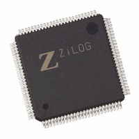
EZ80190AZ050SG Zilog, EZ80190AZ050SG Datasheet - Page 22

EZ80190AZ050SG
Manufacturer Part Number
EZ80190AZ050SG
Description
IC WEBSERVER 8 BIT 50MHZ 100LQFP
Manufacturer
Zilog
Datasheet
1.EZ80190AZ050SG.pdf
(221 pages)
Specifications of EZ80190AZ050SG
Processor Type
eZ80
Features
High Speed, Single-Cycle Instruction-Fetch
Speed
50MHz
Voltage
3.3V
Mounting Type
Surface Mount
Package / Case
100-LQFP
Processor Series
EZ80190x
Core
eZ80
Data Bus Width
8 bit
Program Memory Type
ROMLess
Data Ram Size
8 KB
Interface Type
I2C, IrDA, SPI, UART
Maximum Clock Frequency
50 MHz
Number Of Programmable I/os
32
Number Of Timers
6
Operating Supply Voltage
3 V to 3.6 V
Maximum Operating Temperature
+ 105 C
Mounting Style
SMD/SMT
Minimum Operating Temperature
- 40 C
Lead Free Status / RoHS Status
Lead free / RoHS Compliant
Other names
269-3866
EZ80190AZ050SG
EZ80190AZ050SG
Available stocks
Company
Part Number
Manufacturer
Quantity
Price
Company:
Part Number:
EZ80190AZ050SG
Manufacturer:
ZiLOG
Quantity:
135
- Current page: 22 of 221
- Download datasheet (4Mb)
Table 1. 100-Pin LQFP Pin Identification of the eZ80190 Device (Continued)
PS006614-1208
Pin
No.
50
51
52
53
54
55
56
57
Symbol
NMI
HALT
INSTRD
IORQ
RESET
ZCL
ZDA
PB0
Function
Nonmaskable
Interrupt
Halt
Instruction
READ
Input/Output
Request
Reset
ZDI Clock
ZDI Data
GPIO Port B
Signal Direction
Schmitt Trigger
Input, Active Low
Output, Active Low A Low on this pin indicates the CPU has stopped
Output, Active
Low, tristate
Input/Output,
Active Low
Schmitt Trigger
Input, Active Low
Input with Pull-up
Input/Output,
Open-Drain with
Pull-up
Input/Output
Description
The NMI input is prioritized higher than the
maskable interrupts. It is always recognized at the
end of an instruction, regardless of the state of
the interrupt enable control bits. This input
includes a Schmitt trigger to allow RC rise times.
This external NMI signal is combined with an
internal NMI signal generated from the WDT
block before being connected to the NMI input of
the CPU.
because a HALT instruction is executed.
INSTRD (with MREQ and RD) indicates the
eZ80190 device is fetching an instruction from
code memory. The eZ80190 device does not
drive this line during Reset or bus acknowledge
cycles.
IORQ indicates the CPU is accessing a location
in I/O space. RD and WR indicate the type of
access. The eZ80190 device does not drive this
line during Reset and is an input in bus
acknowledge cycles.
This signal is used to initialize the eZ80190
device. This input must be Low for a minimum of
3 system clock cycles, and must be held Low until
the clock is stable. This input includes a Schmitt
trigger to allow RC rise times.
The ZCL pin is used to clock the data between
the Zilog Debug Interface and the eZ80190
device. This pin features an internal pull-up.
The ZDA pin is used to transfer data between the
Zilog Debug Interface and the eZ80190 device.
This pin is open-drain and features an internal
pull-up.
The PB0 pin can be used for GPIO. It can be
individually programmed as an input or output
and can also be used individually as an interrupt
input. Each Port B pin, when programmed as an
output, can be selected to be an open-drain or
open-source output.
Product Specification
Architectural Overview
12
Related parts for EZ80190AZ050SG
Image
Part Number
Description
Manufacturer
Datasheet
Request
R

Part Number:
Description:
Communication Controllers, ZILOG INTELLIGENT PERIPHERAL CONTROLLER (ZIP)
Manufacturer:
Zilog, Inc.
Datasheet:

Part Number:
Description:
KIT DEV FOR Z8 ENCORE 16K TO 64K
Manufacturer:
Zilog
Datasheet:

Part Number:
Description:
KIT DEV Z8 ENCORE XP 28-PIN
Manufacturer:
Zilog
Datasheet:

Part Number:
Description:
DEV KIT FOR Z8 ENCORE 8K/4K
Manufacturer:
Zilog
Datasheet:

Part Number:
Description:
KIT DEV Z8 ENCORE XP 28-PIN
Manufacturer:
Zilog
Datasheet:

Part Number:
Description:
DEV KIT FOR Z8 ENCORE 4K TO 8K
Manufacturer:
Zilog
Datasheet:

Part Number:
Description:
CMOS Z8 microcontroller. ROM 16 Kbytes, RAM 256 bytes, speed 16 MHz, 32 lines I/O, 3.0V to 5.5V
Manufacturer:
Zilog, Inc.
Datasheet:

Part Number:
Description:
Low-cost microcontroller. 512 bytes ROM, 61 bytes RAM, 8 MHz
Manufacturer:
Zilog, Inc.
Datasheet:

Part Number:
Description:
Z8 4K OTP Microcontroller
Manufacturer:
Zilog, Inc.
Datasheet:

Part Number:
Description:
CMOS SUPER8 ROMLESS MCU
Manufacturer:
Zilog, Inc.
Datasheet:

Part Number:
Description:
SL1866 CMOSZ8 OTP Microcontroller
Manufacturer:
Zilog, Inc.
Datasheet:

Part Number:
Description:
SL1866 CMOSZ8 OTP Microcontroller
Manufacturer:
Zilog, Inc.
Datasheet:

Part Number:
Description:
OTP (KB) = 1, RAM = 125, Speed = 12, I/O = 14, 8-bit Timers = 2, Comm Interfaces Other Features = Por, LV Protect, Voltage = 4.5-5.5V
Manufacturer:
Zilog, Inc.
Datasheet:

Part Number:
Description:
Manufacturer:
Zilog, Inc.
Datasheet:


