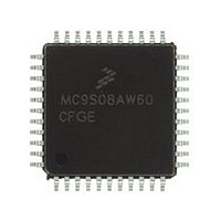
MC9S08AW60CFGE Freescale, MC9S08AW60CFGE Datasheet - Page 230

MC9S08AW60CFGE
Manufacturer Part Number
MC9S08AW60CFGE
Description
Manufacturer
Freescale
Datasheet
1.MC9S08AW60CFGE.pdf
(336 pages)
Specifications of MC9S08AW60CFGE
Cpu Family
HCS08
Device Core Size
8b
Frequency (max)
40MHz
Interface Type
I2C/SCI/SPI
Total Internal Ram Size
2KB
# I/os (max)
34
Number Of Timers - General Purpose
8
Operating Supply Voltage (typ)
3.3/5V
Operating Supply Voltage (max)
5.5V
Operating Supply Voltage (min)
2.7V
On-chip Adc
8-chx10-bit
Instruction Set Architecture
CISC
Operating Temp Range
-40C to 85C
Operating Temperature Classification
Industrial
Mounting
Surface Mount
Pin Count
44
Package Type
LQFP
Program Memory Type
Flash
Program Memory Size
60KB
Lead Free Status / RoHS Status
Compliant
Available stocks
Company
Part Number
Manufacturer
Quantity
Price
Company:
Part Number:
MC9S08AW60CFGE
Manufacturer:
Freescale Semiconductor
Quantity:
10 000
Company:
Part Number:
MC9S08AW60CFGER
Manufacturer:
Freescale Semiconductor
Quantity:
10 000
- Current page: 230 of 336
- Download datasheet (7Mb)
Inter-Integrated Circuit (S08IICV2)
For example, if the bus speed is 8 MHz, the table below shows the possible hold time values with different
ICR and MULT selections to achieve an IIC baud rate of 100kbps.
230
MULT
Field
ICR
7–6
5–0
IIC Multiplier Factor. The MULT bits define the multiplier factor, mul. This factor, along with the SCL divider,
generates the IIC baud rate. The multiplier factor mul as defined by the MULT bits is provided below.
00 mul = 01
01 mul = 02
10 mul = 04
11 Reserved
IIC Clock Rate. The ICR bits are used to prescale the bus clock for bit rate selection. These bits and the MULT
bits determine the IIC baud rate, the SDA hold time, the SCL Start hold time, and the SCL Stop hold time.
Table 13-4
The SCL divider multiplied by multiplier factor mul generates IIC baud rate.
SDA hold time is the delay from the falling edge of SCL (IIC clock) to the changing of SDA (IIC data).
SCL start hold time is the delay from the falling edge of SDA (IIC data) while SCL is high (Start condition) to the
falling edge of SCL (IIC clock).
SCL stop hold time is the delay from the rising edge of SCL (IIC clock) to the rising edge of SDA
SDA (IIC data) while SCL is high (Stop condition).
MULT
provides the SCL divider and hold values for corresponding values of the ICR.
0x2
0x1
0x1
0x0
0x0
SCL Start hold time = bus period (s)
SCL Stop hold time = bus period (s)
Table 13-3. Hold Time Values for 8 MHz Bus Speed
SDA hold time = bus period (s)
Table 13-2. IIC1F Field Descriptions
MC9S08AC16 Series Data Sheet, Rev. 8
0x0B
0x00
0x07
0x14
0x18
ICR
IIC baud rate
3.500
2.500
2.250
2.125
1.125
SDA
=
Description
-------------------------------------------- -
mul
bus speed (Hz)
×
×
×
×
SCLdivider
mul
mul
mul
Hold Times (μs)
×
×
×
SCL Start
SDA hold value
SCL Start hold value
SCL Stop hold value
3.000
4.000
4.000
4.250
4.750
SCL Stop
5.500
5.250
5.250
5.125
5.125
Freescale Semiconductor
Eqn. 13-1
Eqn. 13-2
Eqn. 13-3
Eqn. 13-4
Related parts for MC9S08AW60CFGE
Image
Part Number
Description
Manufacturer
Datasheet
Request
R

Part Number:
Description:
TOWER ELEVATOR BOARDS HARDWARE
Manufacturer:
Freescale Semiconductor
Datasheet:

Part Number:
Description:
TOWER SERIAL I/O HARDWARE
Manufacturer:
Freescale Semiconductor
Datasheet:

Part Number:
Description:
LCD MODULE FOR TWR SYSTEM
Manufacturer:
Freescale Semiconductor
Datasheet:

Part Number:
Description:
DAUGHTER LCD WVGA I.MX51
Manufacturer:
Freescale Semiconductor
Datasheet:

Part Number:
Description:
TOWER SYSTEM BOARD MPC5125
Manufacturer:
Freescale Semiconductor
Datasheet:

Part Number:
Description:
KIT EVALUATION I.MX51
Manufacturer:
Freescale Semiconductor
Datasheet:

Part Number:
Description:
KIT DEVELOPMENT WINCE IMX25
Manufacturer:
Freescale Semiconductor
Datasheet:

Part Number:
Description:
TOWER SYSTEM KIT MPC5125
Manufacturer:
Freescale Semiconductor
Datasheet:

Part Number:
Description:
TOWER SYSTEM BOARD K40X256
Manufacturer:
Freescale Semiconductor
Datasheet:

Part Number:
Description:
TOWER SYSTEM KIT K40X256
Manufacturer:
Freescale Semiconductor
Datasheet:

Part Number:
Description:
Microcontrollers (MCU) MX28 PLATFORM DEV KIT
Manufacturer:
Freescale Semiconductor
Datasheet:

Part Number:
Description:
MCU, MPU & DSP Development Tools IAR KickStart Kit for Kinetis K60
Manufacturer:
Freescale Semiconductor
Datasheet:

Part Number:
Description:
24BIT HDMI MX535/08
Manufacturer:
Freescale Semiconductor
Datasheet:
Part Number:
Description:
Manufacturer:
Freescale Semiconductor, Inc
Datasheet:
Part Number:
Description:
Manufacturer:
Freescale Semiconductor, Inc
Datasheet:


