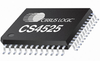
CS4525-CNZR Cirrus Logic Inc, CS4525-CNZR Datasheet - Page 91

CS4525-CNZR
Manufacturer Part Number
CS4525-CNZR
Description
IC PWM Controller+power Stage
Manufacturer
Cirrus Logic Inc
Series
Popguard®r
Type
Class Dr
Datasheet
1.CS4525-CNZ.pdf
(98 pages)
Specifications of CS4525-CNZR
Output Type
2-Channel (Stereo) or 4-Channel (Quad)
Max Output Power X Channels @ Load
30W x 1 @ 4 Ohm; 15W x 2 @ 8 Ohm
Voltage - Supply
8 V ~ 18 V
Features
ADC, Depop, I²C, I²S, Mute, PWM, Short-Circuit and Thermal Protection, Volume Control
Mounting Type
Surface Mount
Package / Case
48-QFN
Lead Free Status / RoHS Status
Lead free / RoHS Compliant
For Use With
598-1586 - REFERENCE BOARD FOR CS4525 PWM
Lead Free Status / RoHS Status
Lead free / RoHS Compliant
Available stocks
Company
Part Number
Manufacturer
Quantity
Price
Part Number:
CS4525-CNZR
Manufacturer:
CIRRUSLOGICINC
Quantity:
20 000
DS726PP3
9.20.4 Amplifier Error Interrupt Bit (AmpErr)
9.20.5 Mask for SRC State (SRCLockM)
9.20.6 Mask for ADC Overflow (ADCOvflM)
9.20.7 Mask for Channel X and Sub Overflow (ChOvflM)
Function:
This bit is read only. When set, indicates that an error was detected in the power amplifier section since
the last read of this register. This interrupt bit is an edge-triggered event and will be cleared following a
read of this register. This bit is the logical OR of all the bits in the amplifier error status register. Read the
amplifier error status register to determine which condition occurred.
If this bit is set, indicating an amplifier stage error condition, and the AmpErrM bit is set to a ‘1’b, the INT
pin will go active. To determine the actual current state of the amplifier error condition, read the amplifier
error status register.
Default = 0
Function:
This bit serves as a mask for the SRC status interrupt source. If this bit is set, the SRCLock interrupt is
unmasked, meaning that if the SRCLock bit is set, the INT pin will go active. If the SRCLockM bit is
cleared, the SRCLock condition is masked, meaning that its occurrence will not affect the INT pin. How-
ever, the SRCLock and SRCLockSt bits will continue to reflect the lock status of the SRC.
Default = 0
Function:
This bit serves as a mask for the ADC overflow interrupt source. If this bit is set, the ADCOvfl interrupt is
unmasked, meaning that if the ADCOvfl bit is set, the INT pin will go active. If the ADCOvflM bit is cleared,
the ADCOvfl condition is masked, meaning that its occurrence will not affect the INT pin. However, the
ADCOvfl and ADCOvflSt bits will continue to reflect the overflow state of the ADC.
Default = 0
Function:
This bit serves as a mask for the channel 1, 2, and Sub overflow interrupt source. If this bit is set, the ChO-
vfl interrupt is unmasked, meaning that if the ChOvfl bit is set, the INT pin will go active. If the ChOvflM bit
is cleared, the ChOvfl condition is masked, meaning that its occurrence will not affect the INT pin. How-
ever, the ChOvfl, ChXOvflSt, and SubOvflSt bits will continue to reflect the overflow state of the individual
channels.
AmpErr Setting
SRCLockM Setting
ADCOvflM Setting
ChOvflM Setting
0 ..........................................An amplifier error condition has not occurred since last read of this register.
1 ..........................................An amplifier error condition has occurred since last read of this register.
0 ..........................................SRCLock condition masked.
1 ..........................................SRCLock condition un-masked.
0 ..........................................ADCOvfl condition masked.
1 ..........................................ADCOvfl condition un-masked.
0 ..........................................ChOvfl condition masked.
1 ..........................................ChOvfl condition un-masked.
Amplifier Error Event Status
SRCLock INT Pin Mask State
ADCOvfl INT Pin Mask State
ChOvfl INT Pin Mask State
CS4525
91


