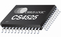
CS4525-CNZR Cirrus Logic Inc, CS4525-CNZR Datasheet - Page 11

CS4525-CNZR
Manufacturer Part Number
CS4525-CNZR
Description
IC PWM Controller+power Stage
Manufacturer
Cirrus Logic Inc
Series
Popguard®r
Type
Class Dr
Datasheet
1.CS4525-CNZ.pdf
(98 pages)
Specifications of CS4525-CNZR
Output Type
2-Channel (Stereo) or 4-Channel (Quad)
Max Output Power X Channels @ Load
30W x 1 @ 4 Ohm; 15W x 2 @ 8 Ohm
Voltage - Supply
8 V ~ 18 V
Features
ADC, Depop, I²C, I²S, Mute, PWM, Short-Circuit and Thermal Protection, Volume Control
Mounting Type
Surface Mount
Package / Case
48-QFN
Lead Free Status / RoHS Status
Lead free / RoHS Compliant
For Use With
598-1586 - REFERENCE BOARD FOR CS4525 PWM
Lead Free Status / RoHS Status
Lead free / RoHS Compliant
Available stocks
Company
Part Number
Manufacturer
Quantity
Price
Part Number:
CS4525-CNZR
Manufacturer:
CIRRUSLOGICINC
Quantity:
20 000
DS726PP3
LVD
DGND
VD_REG
VD
VA_REG
AGND
FILT+
VQ
AFILTL
AFILTR
AINL
AINR
OCREF
PGND
RAMP_CAP
VP
OUT4
OUT3
OUT2
OUT1
TSTO
TWR
ERRUVTE
ERROC
EN_TFB
I2S/LJ
SYS_CLK
TSTO
TSTI
Thermal Pad
25,30,
22,23
27,28
33,34
37,38
31,36
10
11
12
13
14
15
16
17
18
19
20
21
24
26
29
32
35
39
40
41
42
43
44
45
46
47
48
9
-
VD Voltage Level Indicator (Input) - Identifies the voltage level attached to VD. When applying
5.0 V to VD, LVD must be connected to VD. When applying 2.5 V or 3.3 V to VD, LVD must be con-
nected to DGND.
Digital Ground (Input) - Ground for the internal logic and I/O.
Core Logic Power (Output) - Internally generated low voltage power supply for digital logic.
Digital Power (Input) - Positive power supply for the internal regulators and digital I/O.
Analog Power (Output) - Internally generated positive power for the analog section and I/O.
Analog Ground (Input) - Ground reference for the internal analog section and I/O.
Positive Voltage Reference (Output) - Positive reference voltage for the internal ADC sampling
circuits.
Common Mode Voltage (Output) - Filter connection for internal common mode voltage.
Antialias Filter Connection (Output) - Antialias filter connection for ADC inputs.
Analog Input (Input) - The full-scale input level is specified in the ADC Analog Characteristics
specification table.
Over Current Reference Setting (Input) - Sets the reference for over current detection.
Power Ground (Input) - Ground for the individual output power half-bridge devices.
Output Ramp Capacitor (Input) - This pin should be connected directly to VP in hardware mode.
High Voltage Power (Input) - High voltage power supply for the individual half-bridge devices.
PWM Output (Output) - Amplified PWM power outputs.
Test Output (Output) - These pins are outputs used for the Logic Level PWM switching signals
available only in software mode. They must be left unconnected for hardware mode operation.
Thermal Warning Output (Output) - Thermal warning output.
Thermal and Undervoltage Error Output (Output) - Error flag for thermal shutdown and under-
voltage.
Overcurrent Error Output (Output) - Overcurrent error flag.
Enable Thermal Feedback (Input) - Enables the thermal foldback feature when high.
I²S/Left Justified (Input) - Selects between I²S and Left-Justified data format for the serial input
port. Selects I²S when high and LJ when low.
System Clock (Input/Output) -Clock source for the delta-sigma modulators.
Test Output (Output) - This pin is an output used for the crystal oscillator driver available only in
software mode. It must be left unconnected for normal hardware mode operation.
Test Input (Input) - This pin is an input used for the crystal oscillator driver available only in soft-
ware mode. It must be tied to digital ground for normal hardware mode operation.
Thermal Pad - Thermal relief pad for optimized heat dissipation. See
page 65
for more information.
“QFN Thermal Pad” on
CS4525
11


