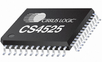
CS4525-CNZR Cirrus Logic Inc, CS4525-CNZR Datasheet - Page 6

CS4525-CNZR
Manufacturer Part Number
CS4525-CNZR
Description
IC PWM Controller+power Stage
Manufacturer
Cirrus Logic Inc
Series
Popguard®r
Type
Class Dr
Datasheet
1.CS4525-CNZ.pdf
(98 pages)
Specifications of CS4525-CNZR
Output Type
2-Channel (Stereo) or 4-Channel (Quad)
Max Output Power X Channels @ Load
30W x 1 @ 4 Ohm; 15W x 2 @ 8 Ohm
Voltage - Supply
8 V ~ 18 V
Features
ADC, Depop, I²C, I²S, Mute, PWM, Short-Circuit and Thermal Protection, Volume Control
Mounting Type
Surface Mount
Package / Case
48-QFN
Lead Free Status / RoHS Status
Lead free / RoHS Compliant
For Use With
598-1586 - REFERENCE BOARD FOR CS4525 PWM
Lead Free Status / RoHS Status
Lead free / RoHS Compliant
Available stocks
Company
Part Number
Manufacturer
Quantity
Price
Part Number:
CS4525-CNZR
Manufacturer:
CIRRUSLOGICINC
Quantity:
20 000
6
LIST OF FIGURES
10. PARAMETER DEFINITIONS .............................................................................................................. 95
11. REFERENCES .................................................................................................................................... 95
12. PACKAGE DIMENSIONS .................................................................................................................. 96
13. THERMAL CHARACTERISTICS ....................................................................................................... 97
14. ORDERING INFORMATION .............................................................................................................. 97
15. REVISION HISTORY .......................................................................................................................... 98
Figure 1.Typical Connection Diagram - Software Mode ........................................................................... 13
Figure 2.Typical Connection Diagram - Hardware Mode .......................................................................... 14
Figure 3.Typical System Configuration 1 .................................................................................................. 15
Figure 4.Typical System Configuration 2 .................................................................................................. 15
Figure 5.Typical System Configuration 3 .................................................................................................. 16
Figure 6.Typical System Configuration 4 .................................................................................................. 17
Figure 7.Serial Audio Input Port Timing .................................................................................................... 21
Figure 8.AUX Serial Port Interface Master Mode Timing .......................................................................... 22
Figure 9.SYS_CLK Timing from Reset ..................................................................................................... 23
Figure 10.PWM_SIGX Timing ................................................................................................................... 23
Figure 11.Control Port Timing - I²C ........................................................................................................... 24
Figure 12.Typical SYS_CLK Input Clocking Configuration ....................................................................... 26
Figure 13.Typical Crystal Oscillator Clocking Configuration ..................................................................... 27
Figure 14.Digital Signal Flow .................................................................................................................... 29
Figure 15.De-Emphasis Filter ................................................................................................................... 31
9.19 Power Control (Address 5Fh) ...................................................................................................... 88
9.20 Interrupt (Address 60h) ............................................................................................................... 89
9.21 Interrupt Status (Address 61h) - Read Only ................................................................................. 92
9.22 Amplifier Error Status (Address 62h) - Read Only ....................................................................... 93
9.23 Device I.D. and Revision (Address 63h) - Read Only .................................................................. 94
13.1 Thermal Flag ................................................................................................................................ 97
9.19.1 Automatic Power Stage Retry (AutoRetry) ......................................................................... 88
9.19.2 Enable Over-Current Protection (EnOCProt) ...................................................................... 88
9.19.3 Select VD Level (SelectVD) ................................................................................................ 88
9.19.4 Power Down ADC (PDnADC) ............................................................................................. 88
9.19.5 Power Down PWM Power Output X (PDnOutX) ................................................................. 89
9.19.6 Power Down (PDnAll) ......................................................................................................... 89
9.20.1 SRC Lock State Transition Interrupt (SRCLock) ................................................................ 90
9.20.2 ADC Overflow Interrupt (ADCOvfl) ..................................................................................... 90
9.20.3 Channel Overflow Interrupt (ChOvfl) .................................................................................. 90
9.20.4 Amplifier Error Interrupt Bit (AmpErr) .................................................................................. 91
9.20.5 Mask for SRC State (SRCLockM) ...................................................................................... 91
9.20.6 Mask for ADC Overflow (ADCOvflM) .................................................................................. 91
9.20.7 Mask for Channel X and Sub Overflow (ChOvflM) ............................................................. 91
9.20.8 Mask for Amplifier Error (AmpErrM) ................................................................................... 92
9.21.1 SRC State Transition (SRCLockSt) .................................................................................... 92
9.21.2 ADC Overflow (ADCOvflSt) ................................................................................................ 92
9.21.3 Sub Overflow (SubOvflSt) ................................................................................................... 92
9.21.4 Channel X Overflow (ChXOvflSt) ........................................................................................ 93
9.21.5 Ramp-Up Cycle Complete (RampDone) ............................................................................ 93
9.22.1 Over-Current Detected On Channel X (OverCurrX) ........................................................... 93
9.22.2 External Amplifier State (ExtAmpSt) ................................................................................... 93
9.22.3 Under Voltage / Thermal Error State (UVTE[1:0]) .............................................................. 94
9.23.1 Device Identification (DeviceID[4:0]) ................................................................................... 94
9.23.2 Device Revision (RevID[2:0]) .............................................................................................. 94
CS4525
DS726PP3


