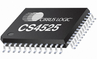
CS4525-CNZR Cirrus Logic Inc, CS4525-CNZR Datasheet - Page 35

CS4525-CNZR
Manufacturer Part Number
CS4525-CNZR
Description
IC PWM Controller+power Stage
Manufacturer
Cirrus Logic Inc
Series
Popguard®r
Type
Class Dr
Datasheet
1.CS4525-CNZ.pdf
(98 pages)
Specifications of CS4525-CNZR
Output Type
2-Channel (Stereo) or 4-Channel (Quad)
Max Output Power X Channels @ Load
30W x 1 @ 4 Ohm; 15W x 2 @ 8 Ohm
Voltage - Supply
8 V ~ 18 V
Features
ADC, Depop, I²C, I²S, Mute, PWM, Short-Circuit and Thermal Protection, Volume Control
Mounting Type
Surface Mount
Package / Case
48-QFN
Lead Free Status / RoHS Status
Lead free / RoHS Compliant
For Use With
598-1586 - REFERENCE BOARD FOR CS4525 PWM
Lead Free Status / RoHS Status
Lead free / RoHS Compliant
Available stocks
Company
Part Number
Manufacturer
Quantity
Price
Part Number:
CS4525-CNZR
Manufacturer:
CIRRUSLOGICINC
Quantity:
20 000
DS726PP3
6.1.4.8
The CS4525 implements a dedicated stereo 24 dB/octave Linkwitz-Riley crossover with adjustable cross-
over frequency to achieve bass management for 2.1 configurations. The filter’s stereo high-pass outputs
are used to drive the full-range speakers, and its stereo low-pass outputs are each attenuated by 6 dB
and summed to drive the sub channel.
The bass management crossover is implemented with one of two preset internal filter sets. One set is op-
timized for a 32 kHz sample rate, and the other is optimized for 44.1 kHz, 48 kHz, and 96 kHz sample
rates. The CS4525 automatically detects the input sample rate and chooses the appropriate filter set to
apply. The available bass management cross-over frequencies are shown in
figured with the BassMgr[2:0] bits in the EQ Config register.
Note that the corner frequency of each filter set scales linearly with the input sample rate.
When the internal ADC is used as the serial audio data source, the input sample rate is nominally 48 kHz
and the corresponding shelving frequency corners are available.
The BassMgr[2:0] bits also allow the bass manager to be disabled. When disabled, the bass management
crossover is bypassed and no signal is presented on the sub channel.
To allow full-range headphone operation, when the HP_DETECT/MUTE pin is configured for headphone
detection (the HP/Mute bit is set), the operation of the bass manager is affected by the active state of the
headphone detection input signal. In this configuration, when the bass manager is enabled, (BassMgr[2:0]
bits not equal to ‘000’) and the headphone detection input signal becomes active, the bass manager will
be automatically disabled. When the headphone detection input signal becomes inactive, the bass man-
ager will be automatically reconfigured to operate as dictated by the BassMgr[2:0] bits.
Referenced Control
BassMgr[2:0] .......................
HP/Mute ..............................
Bass Manager Freq 1
Bass Manager Freq 2
Bass Manager Freq 3
Bass Manager Freq 4
Bass Manager Freq 5
Bass Manager Freq 6
Bass Manager Freq 7
Bass Management
Register Location
“Bass Cross-Over Frequency (BassMgr[2:0])” on page 79
“HP_Detect/Mute Pin Mode (HP/Mute)” on page 70
Table 4. Bass Management Cross-Over Frequencies
32 kHz
120 Hz
160 Hz
200 Hz
240 Hz
280 Hz
320 Hz
80 Hz
Input Sample Rate
44.1 kHz
115 Hz
153 Hz
192 Hz
230 Hz
268 Hz
307 Hz
77 Hz
Table 4
below and are con-
48 kHz, 96 kHz
125 Hz
167 Hz
209 Hz
250 Hz
292 Hz
334 Hz
83 Hz
CS4525
35


