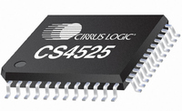
CS4525-CNZR Cirrus Logic Inc, CS4525-CNZR Datasheet - Page 59

CS4525-CNZR
Manufacturer Part Number
CS4525-CNZR
Description
IC PWM Controller+power Stage
Manufacturer
Cirrus Logic Inc
Series
Popguard®r
Type
Class Dr
Datasheet
1.CS4525-CNZ.pdf
(98 pages)
Specifications of CS4525-CNZR
Output Type
2-Channel (Stereo) or 4-Channel (Quad)
Max Output Power X Channels @ Load
30W x 1 @ 4 Ohm; 15W x 2 @ 8 Ohm
Voltage - Supply
8 V ~ 18 V
Features
ADC, Depop, I²C, I²S, Mute, PWM, Short-Circuit and Thermal Protection, Volume Control
Mounting Type
Surface Mount
Package / Case
48-QFN
Lead Free Status / RoHS Status
Lead free / RoHS Compliant
For Use With
598-1586 - REFERENCE BOARD FOR CS4525 PWM
Lead Free Status / RoHS Status
Lead free / RoHS Compliant
Available stocks
Company
Part Number
Manufacturer
Quantity
Price
Part Number:
CS4525-CNZR
Manufacturer:
CIRRUSLOGICINC
Quantity:
20 000
DS726PP3
6.4
6.4.1
Output Filters
The output filter configuration of the CS4525 can greatly affect device performance. These components re-
duce radiated EMI, protect the output transistors of the device, attenuate the high frequency content of the
output signal, and, in the half bridge configuration, block DC current from reaching the loudspeaker.
Half-Bridge Output Filter
Figure 26
implemented as an RC snubber network comprised of a resistor R
(680 pF). This should be placed as close as possible to the corresponding output pin. This circuit decreas-
es the slew rate of the output signal and reduces high frequency ringing which can lead to increased EMI.
The Schottky diodes protect the body diodes of the output devices by conducting load current during
switching transitions; these diodes must be present to ensure proper device operation.
The inductor L1 and capacitor C1 form a low-pass filter to remove high frequency switching content from
the output signal. These values combine with the nominal load impedance of the speaker to set the cut-
off frequency of the filter.
impedance for a corner frequency of approximately 35 kHz (-3 dB).
C2 serves to block DC from the output.
corner frequency (-3 dB) and nominal speaker impedances of 4 Ω, 6 Ω, and 8 Ω. This capacitor should be
chosen to have a ripple current rating higher than the amount of current that will pass through it.
shows the output filter for a half-bridge configuration. A transient voltage suppression circuit is
CS4525
OUTx
Table 19. DC-Blocking Capacitors Values - Half-Bridge
Table 18. Low-Pass Filter Components - Half-Bridge
Table 18
Load
Load
680 pF
4 Ω
6 Ω
8 Ω
4 Ω
6 Ω
8 Ω
5.6 Ω
C
R
Figure 26. Output Filter - Half-Bridge
s
s
shows the component values for L1 and C1 based on nominal speaker
Table 19
VP
Corner Frequency
D1*
D2*
* ROHM RB160 M-30
or equivalent
120 Hz
120 Hz
110 Hz
22 µH
33 µH
47 µH
40 Hz
58 Hz
39 Hz
68 Hz
42 Hz
60 Hz
shows the component values for C2 based on desired
L1
L1
C1
s
1000 µF
(5.6 Ω, 1/8 W) and a capacitor C
0.68 µF
0.47 µF
680 µF
330 µF
680 µF
390 µF
220 µF
470 µF
330 µF
180 µF
1.0 µF
C1
C2
C2
CS4525
59
s


