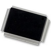
DP83865DVH National Semiconductor, DP83865DVH Datasheet - Page 9

DP83865DVH
Manufacturer Part Number
DP83865DVH
Description
10/100/1000BASE-T TRANSCEIVER, SMD
Manufacturer
National Semiconductor
Specifications of DP83865DVH
Data Rate
1000Mbps
No. Of Ports
1
Ethernet Type
IEEE 802.3u, IEEE 802.3z
Supply Current
430µA
Supply Voltage Range
2.375V To 2.625V, 3.135V To 3.465V
Operating Temperature Range
0°C To +70°C
Interface Type
GMII, MII, RGMII
Rohs Compliant
Yes
Leaded Process Compatible
No
Peak Reflow Compatible (260 C)
No
Lead Free Status / RoHS Status
Lead free / RoHS Compliant
Available stocks
Company
Part Number
Manufacturer
Quantity
Price
Company:
Part Number:
DP83865DVH
Manufacturer:
Texas Instruments
Quantity:
10 000
Company:
Part Number:
DP83865DVH/NOPB
Manufacturer:
NXP
Quantity:
1 000
Company:
Part Number:
DP83865DVH/NOPB
Manufacturer:
Texas Instruments
Quantity:
10 000
1.0 Pin Description
ACTIVITY_LED /
SPEED0_STRAP
LINK10_LED /RLED/
SPEED1_STRAP
LINK100_LED /
DUPLEX_STRAP
LINK1000_LED /
AN_EN_STRAP
Signal Name
I/O,
S, PD
I/O,
S, PD
I/O,
S, PU
I/O,
S, PU
Type
(Continued)
PQFP
Pin #
10
7
8
9
SPEED SELECT STRAP: These strap option pins have 2 different functions
depending on whether Auto-Negotiation is enabled or not.
Auto-Neg disabled:
Auto-Neg enabled (Advertised capability):
Note: The status of this bit is reflected in register 0x10.12.
ACTIVITY LED: The LED output indicates the occurrence of either idle error
or packet transfer.
SPEED SELECT STRAP: The strap option pins have 2 different functions de-
pending on whether Auto-Neg is enabled or not. See SPEED0_STRAP for de-
tails.
Note: The status of this bit is reflected in register 0x10.13.
10M GOOD LINK LED: In the standard 5-LED display mode, this LED output
indicates that the PHY has established a good link at 10 Mbps.
RLED MODE: There are two reduced LED modes, the 3-in-1 and 4-in-1
modes. Each RLED mode is enabled in register 0x13.5 and 0x1A.0.
Note: LED steady on indicates good link and flashing indicates Tx/Rx activities.
DUPLEX MODE: This pin sets the default value for the duplex mode. ‘1’ en-
ables Full Duplex by default, ‘0’ enables Half Duplex only.
Note: The status of this bit is reflected in bit 14 of register 0x10.
100M SPEED AND GOOD LINK LED: The LED output indicates that the PHY
has established a good link at 100 Mbps.
In 100BASE-T mode, the link is established as a result of an input receive am-
plitude compliant with TP-PMD specifications which will result in internal gen-
eration of Signal Detect. LINK100_LED will assert after the internal Signal
Detect has remained asserted for a minimum of 500 s. LINK100_LED will de-
assert immediately following the de-assertion of the internal Signal Detect.
AUTO-NEGOTIATION ENABLE: Input to initialize Auto-Negotiation Enable
bit (register 0 bit-12).
‘1’ enables Auto-Neg and ‘0’ disables Auto-Neg.
Note: The status of this bit is reflected in bit 15 of register 0x10. This pin also
sets the default for and can be overwritten by bit 12 of register 0x00.
1000M SPEED AND GOOD LINK LED: The LED output indicates that the
PHY has established a good link at 1000 Mbps.
In 1000BASE-T mode, the link is established as a result of training, Auto-Ne-
gotiation completed, valid 1000BASE-T link established and reliable reception
of signals transmitted from a remote PHY is received.
– 3-in-1: 10, 100, and 1000 Mbps good links are combined into one LED.
– 4-in-1: 3-in-1 and activity are combined.
Speed[1]
Speed[1]
1
1
0
0
1
1
0
0
9
Speed[0]
Speed[0]
1
0
1
0
1
0
1
0
Description
Speed Enabled
= Reserved
= 1000BASE-T
= 100BASE-TX
= 10BASE-T
Speed Enabled
= 1000BASE-T, 10BASE-T
= 1000BASE-T
= 1000BASE-T, 100BASE-TX
= 1000BASE-T, 100BASE-TX, 10BASE-T
www.national.com


