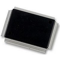
DP83865DVH National Semiconductor, DP83865DVH Datasheet - Page 57

DP83865DVH
Manufacturer Part Number
DP83865DVH
Description
10/100/1000BASE-T TRANSCEIVER, SMD
Manufacturer
National Semiconductor
Specifications of DP83865DVH
Data Rate
1000Mbps
No. Of Ports
1
Ethernet Type
IEEE 802.3u, IEEE 802.3z
Supply Current
430µA
Supply Voltage Range
2.375V To 2.625V, 3.135V To 3.465V
Operating Temperature Range
0°C To +70°C
Interface Type
GMII, MII, RGMII
Rohs Compliant
Yes
Leaded Process Compatible
No
Peak Reflow Compatible (260 C)
No
Lead Free Status / RoHS Status
Lead free / RoHS Compliant
Available stocks
Company
Part Number
Manufacturer
Quantity
Price
Company:
Part Number:
DP83865DVH
Manufacturer:
Texas Instruments
Quantity:
10 000
Company:
Part Number:
DP83865DVH/NOPB
Manufacturer:
NXP
Quantity:
1 000
Company:
Part Number:
DP83865DVH/NOPB
Manufacturer:
Texas Instruments
Quantity:
10 000
4.0 Functional Description
4.7.9 MLT-3 Converter / DAC / Line Driver
The Binary to MLT-3 conversion is accomplished by con-
verting the serial NRZI data stream output from the NRZI
encoder into two binary data streams with alternately
The 100BASE-TX MLT-3 signal sourced by the MDI+/- line
driver output pins is slew rate controlled. This should be
considered when selecting AC coupling magnetics to
ensure TP-PMD Standard compliant transition times (3 ns
< t
The 100BASE-TX transmit TP-PMD function within the
DP83865 outputs only MLT-3 encoded data. Binary data
outputs is not available from the MDI+/- in the 100 Mb/s
mode.
4.7.10 TX_ER
Assertion of the TX_ER input while the TX_EN is also
asserted will cause the DP83865 to substitute HALT code-
groups for the 5B data present at TXD[3:0]. However, the
Start-of-Stream Delimiter (SSD) /J/K/ and End-of-Stream
Delimiter (ESD) /T/R/ will not be substituted with HALT
code-groups. As a result, the assertion of TX_ER while
TX_EN is asserted will result in a frame properly encapsu-
lated with the /J/K/ and /T/R/ delimiters which contains
HALT code-groups in place of the data code-groups.
4.8 10BASE-T and 100BASE-TX Receiver
The 10BASE-T receiver converts Manchester codeing to 4-
bit nibble data to the MII. The 100BASE-TX receiver con-
sists of several sub functional blocks which convert the
scrambled MLT-3 125 Mb/s serial data stream to synchro-
nous 4-bit nibble data that is provided to the MII. The
10/100 Mb/s TP-PMD is integrated with the 1000 Mb/s.
The 10/100 differential input data MDI+/- is routed from
channel B of the isolation magnetics.
See Figure 8 for a block diagram of the 10BASE-T AND
100BASE-TX receive function. It provides an overview of
each functional block within the 10/100 receive section.
The 10BASE-T Receive section consists of the following
functional blocks:
— Receiver
— Clock and Data Recovery
r
< 5 ns).
PAM-17_in
NRZI_in
Manchester
differential MLT-3
Converter
MLT-3_minus
MLT-3
MLT-3_plus
NRZI_in
MLT-3+
MLT-3-
(Continued)
Figure 7. NRZI to MLT-3 conversion
20
MUX
57
10, 100, 1000
phased logic one events. These two binary streams are
then passed to a 10/100/1000 DAC and line driver which
converts the pulses to suitable analog line voltages. Refer
to Figure 8.
DAC
— Manchester Decoder
— Link Detect
The 100BASE-T Receive section consists of the following
functional blocks:
— ADC Block
— Signal Detect
— BLW/EQ/AAC Correction
— Clock Recovery Module
— MLT-3 to NRZ Decoder
— Descrambler
— Serial to Parallel
— 5B/4B Decoder
— Code Group Alignment
— Link Integrity Monitor
Other topics discussed are:
— Bad SSD Detection
— Carrier Sense
— Collision Detect
4.8.1 10BASE-T Receiver
The receiver includes differential buffer, offset and gain
compensation. The receiver provides the signal condition-
ing to the Clock and Data Recovery block.
4.8.2 Clock and Data Recovery
The Clock and Data Recovery block separates the
Manchester encoded data stream into internal clock sig-
nals and data. Once the input exceeds the squelch require-
ments, Carrier Sense (CRS) is asserted off the first edge
presented to the Manchester decoder.
4.8.3 Manchester Decoder
Once the Manchester decoder locks onto the incoming
data stream, it converts Manchester data to NRZ data. The
decoder detects the end of a frame when no more mid-bit
transitions are detected. Within one and a half bit times
Driver
Line
Manchester/
MLT-3/PAM-17
www.national.com


