FSBB15CH60C Fairchild Semiconductor, FSBB15CH60C Datasheet - Page 56
FSBB15CH60C
Manufacturer Part Number
FSBB15CH60C
Description
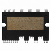
IC POWER MOD SPM 600V SPM27CC
Manufacturer
Fairchild Semiconductor
Series
SPM™r
Type
IGBTr
Specifications of FSBB15CH60C
Configuration
3 Phase
Current
15A
Voltage
600V
Voltage - Isolation
2500Vrms
Package / Case
SPM27CC
Transistor Polarity
N Channel
Dc Collector Current
15A
Collector Emitter Voltage Vces
2V
Power Dissipation Pd
55W
Collector Emitter Voltage V(br)ceo
600V
Operating Temperature Range
-40°C To
Operating Temperature (max)
150C
Operating Temperature (min)
-40C
Pin Count
27
Mounting
Through Hole
Case Length
44mm
Case Height
5.5mm
Screening Level
Automotive
Lead Free Status / RoHS Status
Lead free / RoHS Compliant
Available stocks
Company
Part Number
Manufacturer
Quantity
Price
Company:

Part Number:
FSBB15CH60C
Manufacturer:
CYPRESS
Quantity:
5 610
Part Number:
FSBB15CH60C
Manufacturer:
FSC/ON可看货
Quantity:
20 000


10. Package
10.1 Heat Sink Mounting
device stress, when mounting an SPM on a heat sink.
2008-03-03
Heat Sink
Silicon Grease
Screw Tightening Torque
Heatsink Flatness
Mounting Torque
DBC Flatness
The following precautions should be observed to maximize the effect of the heat sink and minimize
Please follow the instructions of the manufacturer, when attaching a heat sink to an Mini DIP SPM. Be
careful not to apply excessive force to the device when attaching the heat sink.
Drill holes for screws in the heat sink exactly as specified. Smooth the surface by removing burrs and
protrusions of indentations. Refer to Table 10.1.
Heat-sink-equipped devices can become very hot when in operation. Do not touch, as you may sustain
a burn injury.
Apply silicon grease between the SPM and the heat sink to reduce the contact thermal resistance. Be
sure to apply the coating thinly and evenly, do not use too much. A uniform layer of silicon grease (100
~ 200um thickness) should be applied in this situation.
Do not exceed the specified fastening torque. Over tightening the screws may cause package cracks
and bolts and AL heat-fin destruction. Tightening the screws beyond a certain torque can cause
saturation of the contact thermal resistance. The tightening torques in table 10.1 is recommended for
obtaining the proper contact thermal resistance and avoiding the application of excessive stress to the
device.
Avoid stress due to tightening on one side only. Figure 10.1 shows the recommended torque order for
mounting screws. Uneven mounting can cause the SPM DBC substrate to be damaged.
Weight
Item
Mounting Screw : M3
Table 10.1 Torque Rating
(Note Fig. 10.1)
Condition
V4 Mini DIP SPM Application Note (2008-03-03)
Recommended
56
FAIRCHILD SEMICONDUCTOR - Smart Power Module
0.62 N⋅m
-100
Min.
0.51
0
-
Limits
15.40
0.62
Typ
-
+120
1.00
Max
+50
-
Unit
N⋅m
μm
μm
g
Related parts for FSBB15CH60C
Image
Part Number
Description
Manufacturer
Datasheet
Request
R

Part Number:
Description:
Fairchild Semiconductor [IGBT MODULE]
Manufacturer:
Fairchild Semiconductor
Datasheet:

Part Number:
Description:
Discrete Semiconductor Modules
Manufacturer:
Fairchild Semiconductor
Part Number:
Description:
Discrete Semiconductor Modules
Manufacturer:
Fairchild Semiconductor
Part Number:
Description:
This N-Channel MOSFET is produced using Fairchild Semiconductor’s advanced Power Trench® process
Manufacturer:
Fairchild Semiconductor
Datasheet:
Part Number:
Description:
This N-Channel MOSFET is produced using Fairchild Semiconductor’s advanced Power Trench® process
Manufacturer:
Fairchild Semiconductor
Datasheet:
Part Number:
Description:
This N-Channel MOSFET is produced using Fairchild Semiconductor’s advanced PowerTrench® process
Manufacturer:
Fairchild Semiconductor
Datasheet:
Part Number:
Description:
This N-Channel MOSFET is produced using Fairchild Semiconductor’s advanced PowerTrench® process
Manufacturer:
Fairchild Semiconductor
Datasheet:
Part Number:
Description:
This N-Channel MOSFET is produced using Fairchild Semiconductor’s advanced Power Trench® process
Manufacturer:
Fairchild Semiconductor
Datasheet:
Part Number:
Description:
This N-Channel logic Level MOSFETs are produced using Fairchild Semiconductor‘s advanced Power Trench® process that has been special tailored to minimize the on-state resistance and yet maintain superior switching performance
Manufacturer:
Fairchild Semiconductor
Datasheet:
Part Number:
Description:
This N-Channel MOSFET is produced using Fairchild Semiconductor’s advanced Power Trench® process
Manufacturer:
Fairchild Semiconductor
Datasheet:
Part Number:
Description:
This N-Channel SyncFET™ is produced using Fairchild Semiconductor’s advanced PowerTrench® process
Manufacturer:
Fairchild Semiconductor
Datasheet:
Part Number:
Description:
This N-Channel SyncFET™ is produced using Fairchild Semiconductor’s advanced PowerTrench® process
Manufacturer:
Fairchild Semiconductor
Datasheet:
Part Number:
Description:
This N-Channel SyncFET™ is produced using Fairchild Semiconductor’s advanced PowerTrench® process
Manufacturer:
Fairchild Semiconductor
Datasheet:
Part Number:
Description:
This N-Channel logic Level MOSFETs are produced using Fairchild Semiconductor‘s advanced Power Trench® process that has been special tailored to minimize the on-state resistance and yet maintain superior switching performance
Manufacturer:
Fairchild Semiconductor
Datasheet:
Part Number:
Description:
This N-Channel MOSFET is produced using Fairchild Semiconductor’s advanced Power Trench® process that has been especially tailored to minimize the on-state resistance and yet maintain superior switching performance
Manufacturer:
Fairchild Semiconductor
Datasheet: