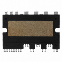
FSBB15CH60C Fairchild Semiconductor, FSBB15CH60C Datasheet - Page 52

FSBB15CH60C
Manufacturer Part Number
FSBB15CH60C
Description
IC POWER MOD SPM 600V SPM27CC
Manufacturer
Fairchild Semiconductor
Series
SPM™r
Type
IGBTr
Specifications of FSBB15CH60C
Configuration
3 Phase
Current
15A
Voltage
600V
Voltage - Isolation
2500Vrms
Package / Case
SPM27CC
Transistor Polarity
N Channel
Dc Collector Current
15A
Collector Emitter Voltage Vces
2V
Power Dissipation Pd
55W
Collector Emitter Voltage V(br)ceo
600V
Operating Temperature Range
-40°C To
Operating Temperature (max)
150C
Operating Temperature (min)
-40C
Pin Count
27
Mounting
Through Hole
Case Length
44mm
Case Height
5.5mm
Screening Level
Automotive
Lead Free Status / RoHS Status
Lead free / RoHS Compliant
Available stocks
Company
Part Number
Manufacturer
Quantity
Price
Company:
Part Number:
FSBB15CH60C
Manufacturer:
CYPRESS
Quantity:
5 610
Part Number:
FSBB15CH60C
Manufacturer:
FSC/ON可看货
Quantity:
20 000
9.4 Heat Sink Design Guide
dissipation, heat sink cost, flow condition around a heat sink, assembly location, etc. In this note, only some
of the constraints are analyzed to give some insights in heat sink selection from a practical application point
of view.
machine applications that have drive characteristics in which the power dissipated is alternatively high and
low over periods of hundreds of milli-seconds in the SPM.
designing the heat sink. This varies widely with the changes in fin spacing, fin/base-plate length and fin/base-
plate width. It should be noted that the optimum fin spacing is approximately 4 or 5 mm with a base-plate
area of 73 × 53 mm
number of fins, i.e., the total convection area. Reducing the fin spacing interferes with the airflow field
between the adjacent fins. This causes an increase in the thermal resistance when the fins are spaced below
and above 4mm and 5mm, respectively. An increase in fin thickness decreases the total number of fins and
the size of the heat sink, resulting in an increase in thermal resistance.
2008-03-03
Heat Sink for Use in Washing Machines
The selection of a heat sink is constrained by many factors including set space, actual operating power
The type of heat sink shown in Fig. 9.9 can be applied under natural convection conditions in washing
Figures 9.10 - 9.13 show the analysis results for the heat sink-to-ambient thermal resistance, R
2
, as shown in Fig. 9.10. Increasing the fin spacing results in a reduction of the total
Figure 9.9 A heat sink example for washing machines applications.
e = Base-plate thickness, f = Base-plate width, g = Base-plate length
a = Fin thickness, b = Fin spacing, c = Fin height, d = Fin length,
f
V4 Mini DIP SPM Application Note (2008-03-03)
52
FAIRCHILD SEMICONDUCTOR - Smart Power Module
c
e
a
d, g
b
θ
ha
, in


