FSBB15CH60C Fairchild Semiconductor, FSBB15CH60C Datasheet - Page 3
FSBB15CH60C
Manufacturer Part Number
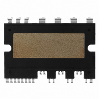
FSBB15CH60C
Description
IC POWER MOD SPM 600V SPM27CC
Manufacturer
Fairchild Semiconductor
Series
SPM™r
Type
IGBTr
Specifications of FSBB15CH60C
Configuration
3 Phase
Current
15A
Voltage
600V
Voltage - Isolation
2500Vrms
Package / Case
SPM27CC
Transistor Polarity
N Channel
Dc Collector Current
15A
Collector Emitter Voltage Vces
2V
Power Dissipation Pd
55W
Collector Emitter Voltage V(br)ceo
600V
Operating Temperature Range
-40°C To
Operating Temperature (max)
150C
Operating Temperature (min)
-40C
Pin Count
27
Mounting
Through Hole
Case Length
44mm
Case Height
5.5mm
Screening Level
Automotive
Lead Free Status / RoHS Status
Lead free / RoHS Compliant
Available stocks
Company
Part Number
Manufacturer
Quantity
Price
Company:

Part Number:
FSBB15CH60C
Manufacturer:
CYPRESS
Quantity:
5 610
Part Number:
FSBB15CH60C
Manufacturer:
FSC/ON可看货
Quantity:
20 000


2008-03-03
8.
9.
10. Package .................................................................................................56
7.1 SPM Functions versus Control Power Supply Voltage................................................................... 29
7.2 Under-Voltage Protection.................................................................................................................. 30
7.3 Short-Circuit Protection .................................................................................................................... 32
7.4 Fault Output Circuit ........................................................................................................................... 36
7.5 TSD (Thermal Shut-Down) Protection.............................................................................................. 37
8.1 Operation of Bootstrap Circuit ......................................................................................................... 37
8.2 Initial Charging of Bootstrap Capacitor ........................................................................................... 38
8.3 Selection of a Bootstrap Capacitor .................................................................................................. 38
8.4 Built in Bootstrap Diode including around 15
8.5 Charging and Discharging of the Bootstrap Capacitor during PWM-Inverter Operation............. 40
8.6 Recommended Boot Strap Operation Circuit and Parameters ...................................................... 41
9.1 Power Loss of SPM ........................................................................................................................... 42
9.2 Thermal Impedance ........................................................................................................................... 44
9.3 Temperature Rise Considerations and Calculation Example......................................................... 51
9.4 Heat Sink Design Guide .................................................................................................................... 52
10.1 Heat Sink Mounting ......................................................................................................................... 56
10.2 Handling Precaution........................................................................................................................ 57
10.3 Marking Specifications.................................................................................................................... 59
10.4 Packaging Specifications................................................................................................................ 61
7.3.1 Timing chart of Short Circuit (SC) Protection ........................................................................... 32
7.3.2 Selecting Current Sensing Shunt Resistor................................................................................ 33
9.1.1 Conduction Loss ......................................................................................................................... 42
9.1.2 Switching Loss ............................................................................................................................ 43
9.2.1 Overview ...................................................................................................................................... 44
9.2.2 Measurement Method.................................................................................................................. 47
9.2.3 Measurement Procedures........................................................................................................... 48
Bootstrap Circuit...................................................................................37
Power Loss and Dissipation ................................................................42
V4 Mini DIP SPM Application Note (2008-03-03)
Ω
3
FAIRCHILD SEMICONDUCTOR - Smart Power Module
Resistance characteristics................................. 39
Related parts for FSBB15CH60C
Image
Part Number
Description
Manufacturer
Datasheet
Request
R

Part Number:
Description:
Fairchild Semiconductor [IGBT MODULE]
Manufacturer:
Fairchild Semiconductor
Datasheet:

Part Number:
Description:
Discrete Semiconductor Modules
Manufacturer:
Fairchild Semiconductor
Part Number:
Description:
Discrete Semiconductor Modules
Manufacturer:
Fairchild Semiconductor
Part Number:
Description:
This N-Channel MOSFET is produced using Fairchild Semiconductor’s advanced Power Trench® process
Manufacturer:
Fairchild Semiconductor
Datasheet:
Part Number:
Description:
This N-Channel MOSFET is produced using Fairchild Semiconductor’s advanced Power Trench® process
Manufacturer:
Fairchild Semiconductor
Datasheet:
Part Number:
Description:
This N-Channel MOSFET is produced using Fairchild Semiconductor’s advanced PowerTrench® process
Manufacturer:
Fairchild Semiconductor
Datasheet:
Part Number:
Description:
This N-Channel MOSFET is produced using Fairchild Semiconductor’s advanced PowerTrench® process
Manufacturer:
Fairchild Semiconductor
Datasheet:
Part Number:
Description:
This N-Channel MOSFET is produced using Fairchild Semiconductor’s advanced Power Trench® process
Manufacturer:
Fairchild Semiconductor
Datasheet:
Part Number:
Description:
This N-Channel logic Level MOSFETs are produced using Fairchild Semiconductor‘s advanced Power Trench® process that has been special tailored to minimize the on-state resistance and yet maintain superior switching performance
Manufacturer:
Fairchild Semiconductor
Datasheet:
Part Number:
Description:
This N-Channel MOSFET is produced using Fairchild Semiconductor’s advanced Power Trench® process
Manufacturer:
Fairchild Semiconductor
Datasheet:
Part Number:
Description:
This N-Channel SyncFET™ is produced using Fairchild Semiconductor’s advanced PowerTrench® process
Manufacturer:
Fairchild Semiconductor
Datasheet:
Part Number:
Description:
This N-Channel SyncFET™ is produced using Fairchild Semiconductor’s advanced PowerTrench® process
Manufacturer:
Fairchild Semiconductor
Datasheet:
Part Number:
Description:
This N-Channel SyncFET™ is produced using Fairchild Semiconductor’s advanced PowerTrench® process
Manufacturer:
Fairchild Semiconductor
Datasheet:
Part Number:
Description:
This N-Channel logic Level MOSFETs are produced using Fairchild Semiconductor‘s advanced Power Trench® process that has been special tailored to minimize the on-state resistance and yet maintain superior switching performance
Manufacturer:
Fairchild Semiconductor
Datasheet:
Part Number:
Description:
This N-Channel MOSFET is produced using Fairchild Semiconductor’s advanced Power Trench® process that has been especially tailored to minimize the on-state resistance and yet maintain superior switching performance
Manufacturer:
Fairchild Semiconductor
Datasheet: