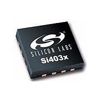
SI4031-B1-FM Silicon Laboratories Inc, SI4031-B1-FM Datasheet - Page 19

SI4031-B1-FM
Manufacturer Part Number
SI4031-B1-FM
Description
IC TX 240-930MHZ -8-13DB 20VQFN
Manufacturer
Silicon Laboratories Inc
Type
ISM Transmitterr
Datasheet
1.SI4031-B1-FMR.pdf
(58 pages)
Specifications of SI4031-B1-FM
Package / Case
20-VQFN
Frequency
240MHz ~ 930MHz
Applications
General Purpose
Modulation Or Protocol
FSK, GFSK, OOK
Data Rate - Maximum
256 kbps
Power - Output
13dBm
Current - Transmitting
30mA
Data Interface
PCB, Surface Mount
Antenna Connector
PCB, Surface Mount
Voltage - Supply
1.8 V ~ 3.6 V
Operating Temperature
-40°C ~ 85°C
Operating Frequency
240 MHz to 930 MHz
Maximum Operating Temperature
+ 85 C
Mounting Style
SMD/SMT
Operating Supply Voltage
1.8 V to 3.6 V
Supply Current
30 mA
Lead Free Status / RoHS Status
Lead free / RoHS Compliant
Features
-
Memory Size
-
Lead Free Status / Rohs Status
Lead free / RoHS Compliant
Available stocks
Company
Part Number
Manufacturer
Quantity
Price
Part Number:
SI4031-B1-FM
Manufacturer:
SILICON LABS/芯科
Quantity:
20 000
Company:
Part Number:
SI4031-B1-FMR
Manufacturer:
INFINEON
Quantity:
12 000
Si4030/31/32-B1
3.2.3. TX State
The TX state may be entered from any of the IDLE modes when the txon bit is set to 1 in "Register 07h. Operating
Mode and Function Control 1". A built-in sequencer takes care of all the actions required to transition between
states from enabling the crystal oscillator to ramping up the PA. The following sequence of events will occur
automatically when going from STANDBY mode to TX mode by setting the txon bit.
1. Enable the main digital LDO and the Analog LDOs.
2. Start up crystal oscillator and wait until ready (controlled by an internal timer).
3. Enable PLL.
4. Calibrate VCO (this action is skipped when the vcocal bit is “0”, default value is “1”).
5. Wait until PLL settles to required transmit frequency (controlled by timer).
6. Activate power amplifier and wait until power ramping is completed (controlled by an internal timer).
7. Transmit packet.
Steps in this sequence may be eliminated depending on which IDLE mode the chip is configured to prior to setting
the txon bit. By default, the VCO and PLL are calibrated every time the PLL is enabled.
3.2.4. Device Status
Add R/W Function/Description
D7
D6
D5
D4
D3
D2
D1
D0
POR Def.
02
R
Device Status
ffovfl
ffunfl
Reserved
Reserved
freqerr
cps[1] cps[0]
—
The operational status of the chip can be read from "Register 02h. Device Status".
Rev 1.1
19


