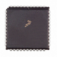
MC68HC711D3CFNE2 Freescale Semiconductor, MC68HC711D3CFNE2 Datasheet - Page 72

MC68HC711D3CFNE2
Manufacturer Part Number
MC68HC711D3CFNE2
Description
IC MCU 8BIT 3MHZ 44-PLCC
Manufacturer
Freescale Semiconductor
Series
HC11r
Specifications of MC68HC711D3CFNE2
Core Processor
HC11
Core Size
8-Bit
Speed
2MHz
Connectivity
SCI, SPI
Peripherals
POR, WDT
Number Of I /o
26
Program Memory Size
4KB (4K x 8)
Program Memory Type
OTP
Ram Size
192 x 8
Voltage - Supply (vcc/vdd)
4.5 V ~ 5.5 V
Oscillator Type
Internal
Operating Temperature
-40°C ~ 85°C
Package / Case
44-PLCC
Lead Free Status / RoHS Status
Lead free / RoHS Compliant
Eeprom Size
-
Data Converters
-
Available stocks
Company
Part Number
Manufacturer
Quantity
Price
Company:
Part Number:
MC68HC711D3CFNE2
Manufacturer:
ALLEGEO
Quantity:
4 492
Company:
Part Number:
MC68HC711D3CFNE2
Manufacturer:
Freescale Semiconductor
Quantity:
10 000
IDLE — Idle Line Detected Flag
OR — Overrun Error Flag
NF — Noise Error Flag
FE — Framing Error Bit
6.7.5 Baud Rate Register
The baud rate register (BAUD) is used to select different baud rates for the SCI system. The SCP1 and
SCP0 bits function as a prescaler for the SCR2–SCR0 bits. Together, these five bits provide multiple baud
rate combinations for a given crystal frequency. Normally, this register is written once during initialization.
The prescaler is set to its fastest rate by default out of reset and can be changed at any time. Refer to
Table 6-1
TCLR — Clear Baud Rate Counters (Test)
RCKB — SCI Baud Rate Clock Check (Test)
72
Serial Communications Interface (SCI)
This flag is set if the RxD line is idle. Once cleared, IDLE is not set again until the RxD line has been
active and becomes idle again. The IDLE flag is inhibited when RWU = 1. Clear IDLE by reading SCSR
with IDLE set and then reading SCDR.
OR is set if a new character is received before a previously received character is read from SCDR.
Clear the OR flag by reading SCSR with OR set and then reading SCDR.
NF is set if majority sample logic detects anything other than a unanimous decision. Clear NF by
reading SCSR with NF set and then reading SCDR.
FE is set when a 0 is detected where a stop bit was expected. Clear the FE flag by reading SCSR with
FE set and then reading SCDR.
0 = RxD line active
1 = RxD line idle
0 = No overrun
1 = Overrun detected
0 = Unanimous decision
1 = Noise detected
0 = Stop bit detected
1 = Zero detected
and
Address:
Table 6-2
Reset:
Read:
Write:
U = Unaffected
$002B
TCLR
Bit 7
0
for normal baud rate selections.
Figure 6-7. Baud Rate Register (BAUD)
0
6
0
MC68HC711D3 Data Sheet, Rev. 2.1
SCP1
5
0
SCP0
4
0
RCKB
3
0
SCR2
U
2
SCR1
U
1
Freescale Semiconductor
SCR0
Bit 0
U


