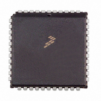
MC68HC711D3CFNE2 Freescale Semiconductor, MC68HC711D3CFNE2 Datasheet - Page 38

MC68HC711D3CFNE2
Manufacturer Part Number
MC68HC711D3CFNE2
Description
IC MCU 8BIT 3MHZ 44-PLCC
Manufacturer
Freescale Semiconductor
Series
HC11r
Specifications of MC68HC711D3CFNE2
Core Processor
HC11
Core Size
8-Bit
Speed
2MHz
Connectivity
SCI, SPI
Peripherals
POR, WDT
Number Of I /o
26
Program Memory Size
4KB (4K x 8)
Program Memory Type
OTP
Ram Size
192 x 8
Voltage - Supply (vcc/vdd)
4.5 V ~ 5.5 V
Oscillator Type
Internal
Operating Temperature
-40°C ~ 85°C
Package / Case
44-PLCC
Lead Free Status / RoHS Status
Lead free / RoHS Compliant
Eeprom Size
-
Data Converters
-
Available stocks
Company
Part Number
Manufacturer
Quantity
Price
Company:
Part Number:
MC68HC711D3CFNE2
Manufacturer:
ALLEGEO
Quantity:
4 492
Company:
Part Number:
MC68HC711D3CFNE2
Manufacturer:
Freescale Semiconductor
Quantity:
10 000
Central Processor Unit (CPU)
A byte is eight bits wide and can be accessed at any byte location. A word is composed of two consecutive
bytes with the most significant byte at the lower value address. Because the M68HC11 is an 8-bit CPU,
there are no special requirements for alignment of instructions or operands.
3.4 Opcodes and Operands
The M68HC11 Family of microcontrollers uses 8-bit opcodes. Each opcode identifies a particular
instruction and associated addressing mode to the CPU. Several opcodes are required to provide each
instruction with a range of addressing capabilities. Only 256 opcodes would be available if the range of
values were restricted to the number able to be expressed in 8-bit binary numbers.
A 4-page opcode map has been implemented to expand the number of instructions. An additional byte,
called a prebyte, directs the processor from page 0 of the opcode map to one of the other three pages.
As its name implies, the additional byte precedes the opcode.
A complete instruction consists of a prebyte, if any, an opcode, and zero, one, two, or three operands.
The operands contain information the CPU needs for executing the instruction. Complete instructions can
be from one to five bytes long.
3.5 Addressing Modes
Six addressing modes can be used to access memory:
These modes are detailed in the following paragraphs. All modes except inherent mode use an effective
address. The effective address is the memory address from which the argument is fetched or stored or
the address from which execution is to proceed. The effective address can be specified within an
instruction, or it can be calculated.
3.5.1 Immediate
In the immediate addressing mode, an argument is contained in the byte(s) immediately following the
opcode. The number of bytes following the opcode matches the size of the register or memory location
being operated on. There are 2-, 3-, and 4- (if prebyte is required) byte immediate instructions. The
effective address is the address of the byte following the instruction.
3.5.2 Direct
In the direct addressing mode, the low-order byte of the operand address is contained in a single byte
following the opcode, and the high-order byte of the address is assumed to be $00. Addresses $00–$FF
are thus accessed directly, using 2-byte instructions. Execution time is reduced by eliminating the
additional memory access required for the high-order address byte. In most applications, this
256-byte area is reserved for frequently referenced data. In M68HC11 MCUs, the memory map can be
configured for combinations of internal registers, RAM, or external memory to occupy these addresses.
38
1. Immediate
2. Direct
3. Extended
4. Indexed
5. Inherent
6. Relative
MC68HC711D3 Data Sheet, Rev. 2.1
Freescale Semiconductor


