D17760BP200ADV Renesas Electronics America, D17760BP200ADV Datasheet - Page 1106
D17760BP200ADV
Manufacturer Part Number
D17760BP200ADV
Description
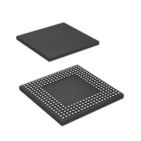
MPU 3V 8K,PB-FREE, 256-BGA
Manufacturer
Renesas Electronics America
Series
SuperH® SH7750r
Datasheet
1.D6417760BP200ADV.pdf
(1418 pages)
Specifications of D17760BP200ADV
Core Processor
SH-4
Core Size
32-Bit
Speed
200MHz
Connectivity
Audio Codec, CAN, EBI/EMI, FIFO, I²C, MFI, MMC, SCI, Serial Sound, SIM, SPI, USB
Peripherals
DMA, LCD, POR, WDT
Number Of I /o
69
Program Memory Type
ROMless
Ram Size
48K x 8
Voltage - Supply (vcc/vdd)
1.4 V ~ 1.6 V
Data Converters
A/D 4x10b
Oscillator Type
Internal
Operating Temperature
-40°C ~ 85°C
Package / Case
256-BGA
Lead Free Status / RoHS Status
Lead free / RoHS Compliant
Eeprom Size
-
Program Memory Size
-
Available stocks
Company
Part Number
Manufacturer
Quantity
Price
Company:

Part Number:
D17760BP200ADV
Manufacturer:
Renesas Electronics America
Quantity:
10 000


Notes: 1. This pin is pulled up in this LSI. Using external pull-up resistors will not affect the use of
The maximum frequency of a TCK (TMS, TDI, and TDO) signal is 20 MHz, or 2 MHz when
boundary scan function is used. Set the TCK clock or the CPG of this LSI so that the frequency of
TCK is lower than the frequency of the peripheral clock of this LSI.
Rev. 2.00 Feb. 12, 2010 Page 1022 of 1330
REJ09B0554-0200
Pin Name
Emulator
2. Design the TRST pin so that it can retain low while the RESET pin is asserted low at a
3. This pin should be connected to ground, the RESET, or another pin that operates in the
4. Pull up these pins when not using them as emulator pins and they are not in the output
interrupts or resets via the H-UDI or emulators on the board.
power on reset and can control reset independently, to use interrupts or resets via the
H-UDI or emulators on the board.
same manner as the RESET pin. However, note that connecting this pin to a ground pin
will cause the following problem. Since the TRST pin is pulled up within this LSI, a weak
current flows when the pin is externally connected to ground. The value of the current is
determined by a resistance of the pull-up MOS for the port pin. Although this current
does not affect the operation of this LSI, it consumes unnecessary power.
state.
Abbreviation
AUDSYNC/
AUDCK/
AUDATA[3] to
AUDATA[0]
I/O
Output Emulator Connection
Function
When bit 13 of IPSELR in the PFC is set to 1,
signals are output to the following pins.
CAN0_TX/AUDATA[0]
CAN1_TX/AUDATA[1]
CAN0_RX/AUDATA[2]
CAN1_RX/AUDATA[3]
CAN0_NERR/AUDCK
CAN1_NERR/AUDSYNC
When bit 12 of IPSELR in the PFC is set to 1,
signals are output to the following pins.
ADTRG/AUDATA[0]
Reserved/AUDATA[1]
Reserved/AUDATA[2]
Reserved/AUDATA[3]
Reserved/AUDCK
Reserved/AUDSYNC
When Not
in Use
Open*
4
Related parts for D17760BP200ADV
Image
Part Number
Description
Manufacturer
Datasheet
Request
R

Part Number:
Description:
KIT STARTER FOR M16C/29
Manufacturer:
Renesas Electronics America
Datasheet:

Part Number:
Description:
KIT STARTER FOR R8C/2D
Manufacturer:
Renesas Electronics America
Datasheet:

Part Number:
Description:
R0K33062P STARTER KIT
Manufacturer:
Renesas Electronics America
Datasheet:

Part Number:
Description:
KIT STARTER FOR R8C/23 E8A
Manufacturer:
Renesas Electronics America
Datasheet:

Part Number:
Description:
KIT STARTER FOR R8C/25
Manufacturer:
Renesas Electronics America
Datasheet:

Part Number:
Description:
KIT STARTER H8S2456 SHARPE DSPLY
Manufacturer:
Renesas Electronics America
Datasheet:

Part Number:
Description:
KIT STARTER FOR R8C38C
Manufacturer:
Renesas Electronics America
Datasheet:

Part Number:
Description:
KIT STARTER FOR R8C35C
Manufacturer:
Renesas Electronics America
Datasheet:

Part Number:
Description:
KIT STARTER FOR R8CL3AC+LCD APPS
Manufacturer:
Renesas Electronics America
Datasheet:
Part Number:
Description:
KIT STARTER FOR RX610
Manufacturer:
Renesas Electronics America
Datasheet:

Part Number:
Description:
KIT STARTER FOR R32C/118
Manufacturer:
Renesas Electronics America
Datasheet:

Part Number:
Description:
KIT DEV RSK-R8C/26-29
Manufacturer:
Renesas Electronics America
Datasheet:

Part Number:
Description:
KIT STARTER FOR SH7124
Manufacturer:
Renesas Electronics America
Datasheet:

Part Number:
Description:
KIT STARTER FOR H8SX/1622
Manufacturer:
Renesas Electronics America
Datasheet:

Part Number:
Description:
KIT DEV FOR SH7203
Manufacturer:
Renesas Electronics America
Datasheet: