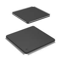
HD6417705F133BV Renesas Electronics America, HD6417705F133BV Datasheet - Page 38

HD6417705F133BV
Manufacturer Part Number
HD6417705F133BV
Description
MPU 3V 0K PB-FREE 208 FP
Manufacturer
Renesas Electronics America
Series
SuperH® SH7700r
Datasheet
1.HD6417705F133BV.pdf
(741 pages)
Specifications of HD6417705F133BV
Core Processor
SH-3
Core Size
32-Bit
Speed
133MHz
Connectivity
EBI/EMI, FIFO, IrDA, SCI, USB
Peripherals
DMA, POR, PWM, WDT
Number Of I /o
105
Program Memory Type
ROMless
Ram Size
32K x 8
Voltage - Supply (vcc/vdd)
1.4 V ~ 1.6 V
Data Converters
A/D 4x10b
Oscillator Type
Internal
Operating Temperature
-20°C ~ 75°C
Package / Case
208-LQFP
Lead Free Status / RoHS Status
Lead free / RoHS Compliant
Eeprom Size
-
Program Memory Size
-
- Current page: 38 of 741
- Download datasheet (5Mb)
Figure 11.10 Hardware Standby Mode (When CA Goes Low in Normal Operation)............... 307
Figure 11.11 Hardware Standby Mode Timing (When CA Goes Low during
WDT Operation while Standby Mode Is Canceled) ............................................ 307
Section 12 Timer Unit (TMU)
Figure 12.1 TMU Block Diagram .......................................................................................... 310
Figure 12.2 Setting Count Operation...................................................................................... 318
Figure 12.3 Auto-Reload Count Operation............................................................................. 319
Figure 12.4 Count Timing when Internal Clock Is Operating.................................................. 319
Figure 12.5 Count Timing when External Clock Is Operating (Both Edges Detected) ............. 320
Figure 12.6 Operation Timing when Using Input Capture Function
(Using TCLK Rising Edge) ................................................................................. 320
Figure 12.7 UNF Set Timing ................................................................................................. 321
Figure 12.8 Status Flag Clear Timing .................................................................................... 321
Section 13 Compare Match Timer (CMT)
Figure 13.1 CMT Block Diagram .......................................................................................... 323
Figure 13.2 Counter Operation .............................................................................................. 326
Figure 13.3 Count Timing ..................................................................................................... 327
Figure 13.4 CMF Set Timing................................................................................................. 327
Section 14 16-Bit Timer Pulse Unit (TPU)
Figure 14.1 Block Diagram of TPU ....................................................................................... 331
Figure 14.2 Example of Counter Operation Setting Procedure................................................ 343
Figure 14.3 Free-Running Counter Operation ........................................................................ 344
Figure 14.4 Periodic Counter Operation................................................................................. 344
Figure 14.5 Example of Setting Procedure for Waveform Output by Compare Match ............. 345
Figure 14.6 Example of 0 Output/1 Output Operation ............................................................ 345
Figure 14.7 Example of Toggle Output Operation.................................................................. 346
Figure 14.8 Compare Match Buffer Operation ....................................................................... 346
Figure 14.9 Example of Buffer Operation Setting Procedure .................................................. 347
Figure 14.10 Example of Buffer Operation ............................................................................ 348
Figure 14.11 Example of PWM Mode Setting Procedure ....................................................... 349
Figure 14.12 Example of PWM Mode Operation (1).............................................................. 350
Figure 14.13 Examples of PWM Mode Operation (2) ............................................................ 350
Section 15 Realtime Clock (RTC)
Figure 15.1 RTC Block Diagram ........................................................................................... 352
Figure 15.2 Setting Time ....................................................................................................... 369
Figure 15.3 Reading the Time................................................................................................ 370
Figure 15.4 Using the Alarm Function ................................................................................... 371
Figure 15.5 Example of Crystal Oscillator Circuit Connection ............................................... 372
Figure 15.6 Using Periodic Interrupt Function ....................................................................... 373
Section 16 Serial Communication Interface with FIFO (SCIF)
Figure 16.1 Block Diagram of SCIF ...................................................................................... 377
Rev. 2.00, 09/03, page xxxvi of xlvi
Related parts for HD6417705F133BV
Image
Part Number
Description
Manufacturer
Datasheet
Request
R

Part Number:
Description:
KIT STARTER FOR M16C/29
Manufacturer:
Renesas Electronics America
Datasheet:

Part Number:
Description:
KIT STARTER FOR R8C/2D
Manufacturer:
Renesas Electronics America
Datasheet:

Part Number:
Description:
R0K33062P STARTER KIT
Manufacturer:
Renesas Electronics America
Datasheet:

Part Number:
Description:
KIT STARTER FOR R8C/23 E8A
Manufacturer:
Renesas Electronics America
Datasheet:

Part Number:
Description:
KIT STARTER FOR R8C/25
Manufacturer:
Renesas Electronics America
Datasheet:

Part Number:
Description:
KIT STARTER H8S2456 SHARPE DSPLY
Manufacturer:
Renesas Electronics America
Datasheet:

Part Number:
Description:
KIT STARTER FOR R8C38C
Manufacturer:
Renesas Electronics America
Datasheet:

Part Number:
Description:
KIT STARTER FOR R8C35C
Manufacturer:
Renesas Electronics America
Datasheet:

Part Number:
Description:
KIT STARTER FOR R8CL3AC+LCD APPS
Manufacturer:
Renesas Electronics America
Datasheet:

Part Number:
Description:
KIT STARTER FOR RX610
Manufacturer:
Renesas Electronics America
Datasheet:

Part Number:
Description:
KIT STARTER FOR R32C/118
Manufacturer:
Renesas Electronics America
Datasheet:

Part Number:
Description:
KIT DEV RSK-R8C/26-29
Manufacturer:
Renesas Electronics America
Datasheet:

Part Number:
Description:
KIT STARTER FOR SH7124
Manufacturer:
Renesas Electronics America
Datasheet:

Part Number:
Description:
KIT STARTER FOR H8SX/1622
Manufacturer:
Renesas Electronics America
Datasheet:

Part Number:
Description:
KIT DEV FOR SH7203
Manufacturer:
Renesas Electronics America
Datasheet:


