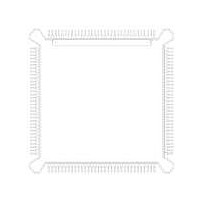
MC68HC16Z1CEH16 Freescale Semiconductor, MC68HC16Z1CEH16 Datasheet - Page 190

MC68HC16Z1CEH16
Manufacturer Part Number
MC68HC16Z1CEH16
Description
IC MCU 16BIT 16MHZ 132-PQFP
Manufacturer
Freescale Semiconductor
Series
HC16r
Specifications of MC68HC16Z1CEH16
Core Processor
CPU16
Core Size
16-Bit
Speed
16MHz
Connectivity
EBI/EMI, SCI, SPI
Peripherals
POR, PWM, WDT
Number Of I /o
16
Program Memory Type
ROMless
Ram Size
1K x 8
Voltage - Supply (vcc/vdd)
2.7 V ~ 5.5 V
Data Converters
A/D 8x10b
Oscillator Type
Internal
Operating Temperature
-40°C ~ 85°C
Package / Case
132-QFP
Processor Series
HC16Z
Core
CPU16
Data Bus Width
16 bit
Controller Family/series
68HC16
No. Of I/o's
26
Ram Memory Size
1KB
Cpu Speed
16MHz
No. Of Timers
2
Embedded Interface Type
QSPI, SCI
Rohs Compliant
Yes
Package
132PQFP
Family Name
HC16
Maximum Speed
16 MHz
Operating Supply Voltage
3.3|5 V
Number Of Programmable I/os
16
On-chip Adc
8-chx10-bit
Number Of Timers
11
Data Ram Size
1 KB
Interface Type
SCI, SPI, UART
Maximum Clock Frequency
16 MHz
Maximum Operating Temperature
+ 85 C
Mounting Style
SMD/SMT
Minimum Operating Temperature
- 40 C
Lead Free Status / RoHS Status
Lead free / RoHS Compliant
Eeprom Size
-
Program Memory Size
-
Lead Free Status / Rohs Status
Lead free / RoHS Compliant
Available stocks
Company
Part Number
Manufacturer
Quantity
Price
Company:
Part Number:
MC68HC16Z1CEH16
Manufacturer:
Freescale Semiconductor
Quantity:
10 000
Part Number:
MC68HC16Z1CEH16
Manufacturer:
FREESCALE
Quantity:
20 000
- Current page: 190 of 500
- Download datasheet (6Mb)
8.5.2 Freeze Mode
8.6 Analog Subsystem
8.6.1 Multiplexer
8-4
STOP is set during system reset, and must be cleared before the ADC can be used.
Because analog circuit bias currents are turned off during low-power stop mode, the
ADC requires recovery time after STOP is cleared.
Execution of the CPU16 LPSTOP command places the entire modular microcontroller
in low-power stop mode. Refer to
When the CPU16 in the modular microcontroller enters background debug mode, the
FREEZE signal is asserted. The type of response is determined by the value of the
FRZ[1:0] field in the ADCMCR.
FREEZE assertion.
When the ADC freezes, the ADC clock stops and all sequential activity ceases.
Contents of control and status registers remain valid while frozen. When the FREEZE
signal is negated, ADC activity resumes.
If the ADC freezes during a conversion, activity resumes with the next step in the con-
version sequence. However, capacitors in the analog conversion circuitry discharge
while the ADC is frozen; as a result, the conversion will be inaccurate.
Refer to
The analog subsystem consists of a multiplexer, sample capacitors, a buffer amplifier,
an RC DAC array, and a high-gain comparator. Comparator output sequences the
successive approximation register (SAR). The interface between the comparator and
the SAR is the boundary between ADC analog and digital subsystems.
The multiplexer selects one of 16 sources for conversion. Eight sources are internal
and eight are external. Multiplexer operation is controlled by channel selection field
CD:CA in register ADCTL1.
sources. The multiplexer contains positive and negative stress protection circuitry.
This circuitry prevents voltages on other input channels from affecting the current con-
version.
4.14.4 Background Debug Mode
FRZ[1:0]
Freescale Semiconductor, Inc.
00
01
10
11
For More Information On This Product,
ANALOG-TO-DIGITAL CONVERTER
Table 8-1 FRZ Field Selection
Go to: www.freescale.com
Ignore FREEZE, continue conversions
Reserved
Finish conversion in process, then freeze
Freeze immediately
Table 8-2
Table 8-1
5.3.4 Low-Power Operation
shows the different multiplexer channel
for more information.
Response
shows the different ADC responses to
for more information.
M68HC16 Z SERIES
USER’S MANUAL
Related parts for MC68HC16Z1CEH16
Image
Part Number
Description
Manufacturer
Datasheet
Request
R
Part Number:
Description:
Manufacturer:
Freescale Semiconductor, Inc
Datasheet:
Part Number:
Description:
Manufacturer:
Freescale Semiconductor, Inc
Datasheet:
Part Number:
Description:
Manufacturer:
Freescale Semiconductor, Inc
Datasheet:
Part Number:
Description:
Manufacturer:
Freescale Semiconductor, Inc
Datasheet:
Part Number:
Description:
Manufacturer:
Freescale Semiconductor, Inc
Datasheet:
Part Number:
Description:
Manufacturer:
Freescale Semiconductor, Inc
Datasheet:
Part Number:
Description:
Manufacturer:
Freescale Semiconductor, Inc
Datasheet:
Part Number:
Description:
Manufacturer:
Freescale Semiconductor, Inc
Datasheet:
Part Number:
Description:
Manufacturer:
Freescale Semiconductor, Inc
Datasheet:
Part Number:
Description:
Manufacturer:
Freescale Semiconductor, Inc
Datasheet:
Part Number:
Description:
Manufacturer:
Freescale Semiconductor, Inc
Datasheet:
Part Number:
Description:
Manufacturer:
Freescale Semiconductor, Inc
Datasheet:
Part Number:
Description:
Manufacturer:
Freescale Semiconductor, Inc
Datasheet:
Part Number:
Description:
Manufacturer:
Freescale Semiconductor, Inc
Datasheet:
Part Number:
Description:
Manufacturer:
Freescale Semiconductor, Inc
Datasheet:


