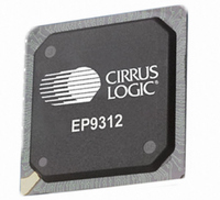
EP9312-CBZ Cirrus Logic Inc, EP9312-CBZ Datasheet - Page 21

EP9312-CBZ
Manufacturer Part Number
EP9312-CBZ
Description
IC ARM9 SOC UNIVERSAL 352PBGA
Manufacturer
Cirrus Logic Inc
Series
EP9r
Specifications of EP9312-CBZ
Core Size
16/32-Bit
Core Processor
ARM9
Speed
200MHz
Connectivity
EBI/EMI, EIDE, Ethernet, I²C, IrDA, Keypad/Touchscreen, SPI, UART/USART, USB
Peripherals
AC'97, DMA, I²:S, LCD, LED, MaverickKey, POR, PWM, WDT
Number Of I /o
16
Program Memory Type
ROMless
Ram Size
32K x 8
Voltage - Supply (vcc/vdd)
1.65 V ~ 3.6 V
Data Converters
A/D 8x12b
Oscillator Type
External
Operating Temperature
0°C ~ 70°C
Package / Case
352-BGA
Controller Family/series
(ARM9)
No. Of I/o's
16
Ram Memory Size
16MB
Cpu Speed
200MHz
No. Of Timers
4
No. Of Pwm Channels
2
Digital Ic Case Style
BGA
Embedded Interface Type
AC97, I2S, SPI, UART, USB
Rohs Compliant
Yes
Processor Series
EP93xx
Core
ARM920T
Data Bus Width
32 bit
3rd Party Development Tools
MDK-ARM, RL-ARM, ULINK2
Lead Free Status / RoHS Status
Lead free / RoHS Compliant
Eeprom Size
-
Program Memory Size
-
Lead Free Status / Rohs Status
Details
Other names
598-1258
Available stocks
Company
Part Number
Manufacturer
Quantity
Price
- Current page: 21 of 824
- Download datasheet (13Mb)
DS785UM1
Table 17-5. UART2 / IrDA Modes .............................................................................................................17-21
Table 17-6. IrDA Service Memory Accesses / Second .............................................................................17-22
Table 18-1. Timers Register Map................................................................................................................18-2
Table 19-1. Watchdog Timer Register Memory Map ..................................................................................19-3
Table 20-1. Real Time Clock Register Memory Map ..................................................................................20-4
Table 21-1. I
Table 21-2. Audio Interfaces Pin Assignment .............................................................................................21-2
Table 21-3. Transmitter FIFO’s ...................................................................................................................21-3
Table 21-4. I2SClkDiv SYSCON Register Effect on I
Table 21-5. Bit Clock Rate Generation........................................................................................................21-9
Table 21-6. FIFO Flags .............................................................................................................................21-12
Table 21-7. I
Table 21-8. I
Table 21-9. I
Table 22-1. AC’97 Input and Output Signals...............................................................................................22-1
Table 22-2. AC’97 Register Memory Map ...................................................................................................22-5
Table 22-3. Interaction Between RSIZE and CM ........................................................................................22-9
Table 22-4. Interaction Between RSIZE and CM Bits ...............................................................................22-11
Table 23-1. SSP Register Memory Map Description.................................................................................23-13
Table 24-1. Static Programming Steps .......................................................................................................24-2
Table 24-2. Dynamic Programming Steps ..................................................................................................24-3
Table 24-3. PWM Registers Map ................................................................................................................24-3
Table 25-1. Switch Definitions and Logical Safeguards to Prevent Physical Damage................................25-3
Table 25-2. Touch Screen Switch Register Configurations.........................................................................25-7
Table 25-3. External Signal Functions ......................................................................................................25-16
Table 25-4. Analog Touch Screen Register Memory Map ........................................................................25-17
Table 26-1. Keypad Interface Register Memory Map..................................................................................26-6
Table 27-1. IDE Host to IDE Interface Definition.........................................................................................27-2
Table 27-2. IDE Cycle Times and Data Transfer Rates ..............................................................................27-7
Table 27-3. Wait State Value for the DMA M2M Register Control.PWSC ..................................................27-8
Table 27-4. HCLK Cycles to De-assert DMA Request................................................................................27-8
Table 27-5. Maximum Theoretical Bandwidths for Various Operating Modes ............................................27-9
Table 27-6. IDE Interface Register Map....................................................................................................27-10
Table 28-1. EP9301 and EP9302 GPIO Port to Pin Map............................................................................28-6
Table 28-2. EP9307 GPIO Port to Pin Map.................................................................................................28-6
Table 28-3. EP9312 GPIO Port to Pin Map.................................................................................................28-7
Table 28-4. EP9315 GPIO Port to Pin Map.................................................................................................28-8
2
2
2
2
S Controller Input and Output Signals ...................................................................................21-2
S TX Registers ....................................................................................................................21-12
S RX Registers ....................................................................................................................21-19
S Configuration and Status Registers .................................................................................21-25
©
Copyright 2007 Cirrus Logic, Inc.
2
S Clock Generation................................................21-8
EP93xx User’s Guide
xxi
Related parts for EP9312-CBZ
Image
Part Number
Description
Manufacturer
Datasheet
Request
R

Part Number:
Description:
IC ARM920T MCU 200MHZ 352-PBGA
Manufacturer:
Cirrus Logic Inc
Datasheet:

Part Number:
Description:
System-on-Chip Processor
Manufacturer:
Cirrus Logic Inc
Datasheet:

Part Number:
Description:
IC ARM920T MCU 200MHZ 352-PBGA
Manufacturer:
Cirrus Logic Inc
Datasheet:

Part Number:
Description:
Development Kit
Manufacturer:
Cirrus Logic Inc
Datasheet:

Part Number:
Description:
Development Kit
Manufacturer:
Cirrus Logic Inc
Datasheet:

Part Number:
Description:
High-efficiency PFC + Fluorescent Lamp Driver Reference Design
Manufacturer:
Cirrus Logic Inc
Datasheet:

Part Number:
Description:
Development Kit
Manufacturer:
Cirrus Logic Inc
Datasheet:

Part Number:
Description:
Development Kit
Manufacturer:
Cirrus Logic Inc
Datasheet:

Part Number:
Description:
Development Kit
Manufacturer:
Cirrus Logic Inc
Datasheet:

Part Number:
Description:
Development Kit
Manufacturer:
Cirrus Logic Inc
Datasheet:

Part Number:
Description:
Development Kit
Manufacturer:
Cirrus Logic Inc
Datasheet:

Part Number:
Description:
Development Kit
Manufacturer:
Cirrus Logic Inc
Datasheet:

Part Number:
Description:
Ref Bd For Speakerbar MSA & DSP Products
Manufacturer:
Cirrus Logic Inc


