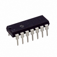
PIC16F688-I/P Microchip Technology, PIC16F688-I/P Datasheet - Page 28

PIC16F688-I/P
Manufacturer Part Number
PIC16F688-I/P
Description
IC PIC MCU FLASH 4KX14 14DIP
Manufacturer
Microchip Technology
Series
PIC® 16Fr
Datasheets
1.PIC16F616T-ISL.pdf
(8 pages)
2.PIC16F688T-ISL.pdf
(204 pages)
3.PIC16F688T-ISL.pdf
(6 pages)
4.PIC16F688T-ISL.pdf
(4 pages)
5.PIC16F688T-ISL.pdf
(688 pages)
6.PIC16F688-EP.pdf
(174 pages)
Specifications of PIC16F688-I/P
Program Memory Type
FLASH
Program Memory Size
7KB (4K x 14)
Package / Case
14-DIP (0.300", 7.62mm)
Core Processor
PIC
Core Size
8-Bit
Speed
20MHz
Connectivity
UART/USART
Peripherals
Brown-out Detect/Reset, POR, WDT
Number Of I /o
12
Eeprom Size
256 x 8
Ram Size
256 x 8
Voltage - Supply (vcc/vdd)
2 V ~ 5.5 V
Data Converters
A/D 8x10b
Oscillator Type
Internal
Operating Temperature
-40°C ~ 85°C
Processor Series
PIC16F
Core
PIC
Data Bus Width
8 bit
Data Ram Size
256 B
Interface Type
SCI/USART
Maximum Clock Frequency
20 MHz
Number Of Programmable I/os
12
Number Of Timers
2
Operating Supply Voltage
2 V to 5.5 V
Maximum Operating Temperature
+ 85 C
Mounting Style
Through Hole
3rd Party Development Tools
52715-96, 52716-328, 52717-734
Development Tools By Supplier
PG164130, DV164035, DV244005, DV164005, PG164120, ICE2000, DM163014, DM164120-4
Minimum Operating Temperature
- 40 C
On-chip Adc
8-ch x 10-bit
Data Rom Size
256 B
Height
3.3 mm
Length
19.05 mm
Supply Voltage (max)
5.5 V
Supply Voltage (min)
2 V
Width
6.35 mm
Lead Free Status / RoHS Status
Lead free / RoHS Compliant
For Use With
AC162066 - HEADER INTRFC MPLAB ICD2 20PINAC162061 - HEADER INTRFC MPLAB ICD2 20PINDM163029 - BOARD PICDEM FOR MECHATRONICSAC162056 - HEADER INTERFACE ICD2 16F688ACICE0207 - MPLABICE 14P 300 MIL ADAPTERAC124001 - MODULE SKT PROMATEII 8DIP/SOIC
Lead Free Status / Rohs Status
Lead free / RoHS Compliant
Available stocks
Company
Part Number
Manufacturer
Quantity
Price
Company:
Part Number:
PIC16F688-I/P
Manufacturer:
MICROCHIP
Quantity:
26
Company:
Part Number:
PIC16F688-I/P
Manufacturer:
MOT
Quantity:
61
PIC16F688
3.4.3
The Low-Frequency Internal Oscillator (LFINTOSC) is
an uncalibrated (approximate) 31 kHz internal clock
source.
The output of the LFINTOSC connects to a postscaler
and multiplexer (see Figure 3-1). 31 kHz can be
selected via software using the IRCF bits (see
Section 3.4.4 “Frequency Select Bits (IRCF)”). The
LFINTOSC is also the frequency for the Power-up
Timer (PWRT), Watchdog Timer (WDT) and Fail-Safe
Clock Monitor (FSCM).
The LFINTOSC is enabled by selecting 31 kHz
(IRCF = 000) as the system clock source (SCS = 1), or
when any of the following are enabled:
• Two-Speed Start-up (IESO = 1 and IRCF = 000)
• Power-up Timer (PWRT)
• Watchdog Timer (WDT)
• Fail-Safe Clock Monitor (FSCM)
The LF Internal Oscillator (LTS) bit (OSCCON<1>)
indicates whether the LFINTOSC is stable or not.
3.4.4
The output of the 8 MHz HFINTOSC and 31 kHz
LFINTOSC connect to a postscaler and multiplexer
(see Figure 3-1). The Internal Oscillator Frequency
select bits, IRCF<2:0> (OSCCON<6:4>), select the
frequency output of the internal oscillators. One of eight
frequencies can be selected via software:
• 8 MHz
• 4 MHz (Default after Reset)
• 2 MHz
• 1 MHz
• 500 kHz
• 250 kHz
• 125 kHz
• 31 kHz
DS41203B-page 26
Note:
LFINTOSC
FREQUENCY SELECT BITS (IRCF)
Following any Reset, the IRCF bits are set
to ‘110’ and the frequency selection is set
to 4 MHz. The user can modify the IRCF
bits to select a different frequency.
Preliminary
3.4.5
When switching between the LFINTOSC and the
HFINTOSC, the new oscillator may already be shut
down to save power. If this is the case, there is a 10 s
delay after the IRCF bits are modified before the
frequency selection takes place. The LTS/HTS bits will
reflect the current active status of the LFINTOSC and
the HFINTOSC oscillators. The timing of a frequency
selection is as follows:
1.
2.
3.
4.
5.
6.
If the internal oscillator speed selected is between
8 MHz and 125 kHz, there is no start-up delay before
the new frequency is selected. This is because the old
and the new frequencies are derived from the
HFINTOSC via the postscaler and multiplexer.
IRCF bits are modified.
If the new clock is shut down, a 10 s clock
start-up delay is started.
Clock switch circuitry waits for a falling edge of
the current clock.
CLKOUT is held low and the clock switch
circuitry waits for a rising edge in the new clock.
CLKOUT is now connected with the new clock.
HTS/LTS bits are updated as required.
Clock switch is complete.
HF AND LF INTOSC CLOCK
SWITCH TIMING
2004 Microchip Technology Inc.


