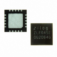
ZLF645E0Q2064G Zilog, ZLF645E0Q2064G Datasheet - Page 77

ZLF645E0Q2064G
Manufacturer Part Number
ZLF645E0Q2064G
Description
IC MCU 64K FLASH 1K RAM 20-QFN
Manufacturer
Zilog
Series
Crimzon™ ZLFr
Specifications of ZLF645E0Q2064G
Core Processor
Z8 LXMC
Core Size
8-Bit
Speed
8MHz
Connectivity
UART/USART
Peripherals
Brown-out Detect/Reset, HLVD, POR, WDT
Number Of I /o
16
Program Memory Size
64KB (64K x 8)
Program Memory Type
FLASH
Ram Size
1K x 8
Voltage - Supply (vcc/vdd)
1.9 V ~ 3.6 V
Operating Temperature
0°C ~ 70°C
Package / Case
20-VQFN Exposed Pad, 20-HVQFN, 20-SQFN, 20-DHVQFN
Lead Free Status / RoHS Status
Lead free / RoHS Compliant
Eeprom Size
-
Data Converters
-
Oscillator Type
-
Other names
269-4723
Available stocks
Company
Part Number
Manufacturer
Quantity
Price
Company:
Part Number:
ZLF645E0Q2064G
Manufacturer:
Maxim
Quantity:
28
- Current page: 77 of 197
- Download datasheet (3Mb)
PS026407-0408
Byte Programming
do not match, the controller reverts to a locked state. If the two writes match, the selected
page becomes active. See
After unlocking a specific page, you can enable either Page Program or Page Erase. For
Flash main memory, writing the value
resides in a sector that is not protected. For Flash Information Area, without sector level
protection, writing the value
Control register locks the Flash Controller.
After unlocking a specific page, you can write to any byte on that page. After a byte is
written the page remains unlocked, allowing for subsequent writes to other bytes on the
same page. Further writes to the Flash Control register causes the active page to revert to a
locked state.
Sector Based Flash Protection
The final protection mechanism for Flash main memory is implemented on a per-sector
basis. For all ZLF645 products, each sector contains 16 pages (of 512 bytes each).
The Sector Protect register controls the protection state of each Flash sector. This register
is address-shared with the Page Select register. It is accessed by unlocking the Flash
Controller by writing the command byte
02H
The Sector Protect register is initialized to 0 on reset, putting each sector into an
unprotected state. When a bit in the Sector Protect register is written to 1, the
corresponding sector can no longer be written or erased. After a bit of the Sector Protect
register has been set, it cannot be cleared except by powering down the device. As
mentioned earlier, sector-based protection is not applicable to the Flash Information Area.
As mentioned previously, all Flash accesses either through user code or through the ICP
interface occur using the Flash memory byte mode of operation. The Flash memory is
enabled for byte programming after unlocking the Flash Controller and enabling either
Mass Erase or Page Erase. When the Flash Controller is unlocked and Mass Erase is
enabled, all Program Memory locations are available for byte programming. In contrast,
when the Flash Controller is unlocked and Page Erase is enabled, only the locations of the
selected page are available for byte programming. An erased Flash byte contains all 1’s
(
Part Number
ZLF645xxxxx32
ZLF645xxxxx64
FFH
targets the Sector Protect register.
).
Number of Sectors
Figure 20
95H
8
4
causes a Page Erase. Any other value written to the Flash
on page 67 for details.
95H
5EH
causes a Page Erase only if the active page
. The next write to Bank F, Register Address
ZLF645 Series Flash MCUs
Product Specification
Flash Controller Operation
69
Related parts for ZLF645E0Q2064G
Image
Part Number
Description
Manufacturer
Datasheet
Request
R

Part Number:
Description:
Microcontrollers (MCU) Zlf645 (32K 20L Ssop F645 (32K 20L Ssop )
Manufacturer:
Maxim Integrated Products

Part Number:
Description:
Microcontrollers (MCU) Crimzon Flash Infrared MCU
Manufacturer:
Maxim Integrated Products

Part Number:
Description:
Microcontrollers (MCU) Crimzon Flash Infrared MCU
Manufacturer:
Maxim Integrated Products

Part Number:
Description:
Microcontrollers (MCU) Crimzon Flash Infrared MCU
Manufacturer:
Maxim Integrated Products

Part Number:
Description:
Microcontrollers (MCU) Crimzon Flash Infrared MCU
Manufacturer:
Maxim Integrated Products

Part Number:
Description:
Microcontrollers (MCU) Crimzon Flash Infrared MCU
Manufacturer:
Maxim Integrated Products

Part Number:
Description:
Microcontrollers (MCU) Crimzon Flash Infrared MCU
Manufacturer:
Maxim Integrated Products

Part Number:
Description:
Microcontrollers (MCU) Crimzon Flash Infrared MCU
Manufacturer:
Maxim Integrated Products

Part Number:
Description:
Microcontrollers (MCU) Crimzon Flash Infrared MCU
Manufacturer:
Maxim Integrated Products

Part Number:
Description:
Microcontrollers (MCU) Crimzon Flash Infrared MCU
Manufacturer:
Maxim Integrated Products

Part Number:
Description:
Microcontrollers (MCU) Crimzon Flash Infrared MCU
Manufacturer:
Maxim Integrated Products

Part Number:
Description:
Microcontrollers (MCU) Crimzon Flash Infrared MCU
Manufacturer:
Maxim Integrated Products

Part Number:
Description:
Microcontrollers (MCU) Crimzon Flash Infrared MCU
Manufacturer:
Maxim Integrated Products

Part Number:
Description:
Microcontrollers (MCU) Crimzon Flash Infrared MCU
Manufacturer:
Maxim Integrated Products

Part Number:
Description:
Microcontrollers (MCU) Crimzon Flash Infrared MCU
Manufacturer:
Maxim Integrated Products


