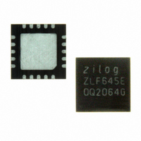
ZLF645E0Q2064G Zilog, ZLF645E0Q2064G Datasheet - Page 174

ZLF645E0Q2064G
Manufacturer Part Number
ZLF645E0Q2064G
Description
IC MCU 64K FLASH 1K RAM 20-QFN
Manufacturer
Zilog
Series
Crimzon™ ZLFr
Specifications of ZLF645E0Q2064G
Core Processor
Z8 LXMC
Core Size
8-Bit
Speed
8MHz
Connectivity
UART/USART
Peripherals
Brown-out Detect/Reset, HLVD, POR, WDT
Number Of I /o
16
Program Memory Size
64KB (64K x 8)
Program Memory Type
FLASH
Ram Size
1K x 8
Voltage - Supply (vcc/vdd)
1.9 V ~ 3.6 V
Operating Temperature
0°C ~ 70°C
Package / Case
20-VQFN Exposed Pad, 20-HVQFN, 20-SQFN, 20-DHVQFN
Lead Free Status / RoHS Status
Lead free / RoHS Compliant
Eeprom Size
-
Data Converters
-
Oscillator Type
-
Other names
269-4723
Available stocks
Company
Part Number
Manufacturer
Quantity
Price
Company:
Part Number:
ZLF645E0Q2064G
Manufacturer:
Maxim
Quantity:
28
- Current page: 174 of 197
- Download datasheet (3Mb)
Flash Option Bits
PS026407-0408
Operation
Option Bit Shadow Register Loading By Reset
Programmable Flash Option Bits allow user configuration of certain aspects of ZLF645
MCU functionality. This configuration data is stored in the Flash memory Information
Block and then read into option byte shadow registers during the last portion of the
ZLF645 MCUs reset period.
Features available for control through the Flash Option Bits include:
•
•
•
•
•
•
•
•
•
•
•
•
For each Flash memory option bit, there is an associated option bit shadow register that is
used to register the value of the option bit. The output of the option bit shadow registers
are used by the ZLF645 MCU to enable various features and functions for the ZLF645
MCU. Each time the Flash Memory Information Block Option Bits are programmed or
erased, the device must be reset for the change in ZLF645 configuration to take effect.
A POR or Stop Mode Recovery Reset with SMR bit 5 set to 1, loads the option bits from
the Flash memory to the Option Bit Shadow registers during the last few clock cycles of
the reset period. In some cases, in order to provide a required value before being loaded,
the Option Bit Shadow registers are reset to a predefined value on the start of the reset
period.
Port 0 low nibble pull-ups
Port 0 high nibble pull-ups
Port 1 low nibble pull-ups
Port 1 high nibble pull-ups
Port 2 pull-ups
Port 3 low nibble pull-ups
Port 4 pull-ups
WDT always enabled
Flash protect entire main memory
Flash protect lower half main memory
XTAL1 to System Clock (no division enable)
16-bit Stack addressiblity enable
ZLF645 Series Flash MCUs
Product Specification
Flash Option Bits
166
Related parts for ZLF645E0Q2064G
Image
Part Number
Description
Manufacturer
Datasheet
Request
R

Part Number:
Description:
Microcontrollers (MCU) Zlf645 (32K 20L Ssop F645 (32K 20L Ssop )
Manufacturer:
Maxim Integrated Products

Part Number:
Description:
Microcontrollers (MCU) Crimzon Flash Infrared MCU
Manufacturer:
Maxim Integrated Products

Part Number:
Description:
Microcontrollers (MCU) Crimzon Flash Infrared MCU
Manufacturer:
Maxim Integrated Products

Part Number:
Description:
Microcontrollers (MCU) Crimzon Flash Infrared MCU
Manufacturer:
Maxim Integrated Products

Part Number:
Description:
Microcontrollers (MCU) Crimzon Flash Infrared MCU
Manufacturer:
Maxim Integrated Products

Part Number:
Description:
Microcontrollers (MCU) Crimzon Flash Infrared MCU
Manufacturer:
Maxim Integrated Products

Part Number:
Description:
Microcontrollers (MCU) Crimzon Flash Infrared MCU
Manufacturer:
Maxim Integrated Products

Part Number:
Description:
Microcontrollers (MCU) Crimzon Flash Infrared MCU
Manufacturer:
Maxim Integrated Products

Part Number:
Description:
Microcontrollers (MCU) Crimzon Flash Infrared MCU
Manufacturer:
Maxim Integrated Products

Part Number:
Description:
Microcontrollers (MCU) Crimzon Flash Infrared MCU
Manufacturer:
Maxim Integrated Products

Part Number:
Description:
Microcontrollers (MCU) Crimzon Flash Infrared MCU
Manufacturer:
Maxim Integrated Products

Part Number:
Description:
Microcontrollers (MCU) Crimzon Flash Infrared MCU
Manufacturer:
Maxim Integrated Products

Part Number:
Description:
Microcontrollers (MCU) Crimzon Flash Infrared MCU
Manufacturer:
Maxim Integrated Products

Part Number:
Description:
Microcontrollers (MCU) Crimzon Flash Infrared MCU
Manufacturer:
Maxim Integrated Products

Part Number:
Description:
Microcontrollers (MCU) Crimzon Flash Infrared MCU
Manufacturer:
Maxim Integrated Products


