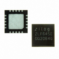
ZLF645E0Q2064G Zilog, ZLF645E0Q2064G Datasheet - Page 176

ZLF645E0Q2064G
Manufacturer Part Number
ZLF645E0Q2064G
Description
IC MCU 64K FLASH 1K RAM 20-QFN
Manufacturer
Zilog
Series
Crimzon™ ZLFr
Specifications of ZLF645E0Q2064G
Core Processor
Z8 LXMC
Core Size
8-Bit
Speed
8MHz
Connectivity
UART/USART
Peripherals
Brown-out Detect/Reset, HLVD, POR, WDT
Number Of I /o
16
Program Memory Size
64KB (64K x 8)
Program Memory Type
FLASH
Ram Size
1K x 8
Voltage - Supply (vcc/vdd)
1.9 V ~ 3.6 V
Operating Temperature
0°C ~ 70°C
Package / Case
20-VQFN Exposed Pad, 20-HVQFN, 20-SQFN, 20-DHVQFN
Lead Free Status / RoHS Status
Lead free / RoHS Compliant
Eeprom Size
-
Data Converters
-
Oscillator Type
-
Other names
269-4723
Available stocks
Company
Part Number
Manufacturer
Quantity
Price
Company:
Part Number:
ZLF645E0Q2064G
Manufacturer:
Maxim
Quantity:
28
- Current page: 176 of 197
- Download datasheet (3Mb)
Table 85. User Option Byte 0 Shadow Register (OPT0SR)
PS026407-0408
Bit
Field
Reset State
CPU Access (R/W)
Register Address (R/W)
Note:
Note:
User Option Byte 1 and Option Byte 1 Shadow Register
Definitions
User Option byte allows the enabling of various features including protecting the Flash’s
main memory from read operations through either of the ZLF645’s Flash access inter-
faces. For it’s associated shadow registers, until the registers are loaded with their corre-
sponding option bit values, their outputs will be in an unknown state.
Table 86
This byte can be programmed and erased (by Page 3 erase) only through the ICP.
During device Power-on Reset, bit 1 and bit 0 value of this Flash Option byte are sampled
into flip-flops, whose outputs control the Flash memory protect function. User codes can
read the flip-flop values, by reading from a uniquely assigned peripheral register address.
User codes cannot over-write the flip-flop values to change this Flash memory protect
function.
describes User Option byte 1 function.
P2PU = 1: Port 2 Pull-ups disabled.
P2PU = 0: Port 2 Pull-ups enabled.
P1HPU = 1: Port 1 high nibble Pull-ups disabled
P1HPU = 0: Port 1 high nibble Pull-ups enabled.
P1LPU = 1: Port 1 low nibble Pull-ups disabled.
P1LPU = 0: Port 1 low nibble Pull-ups enabled.
P0HPU = 1: Port 0 high nibble Pull-ups disabled.
P0HPU = 0: Port 0 high nibble Pull-ups enabled.
P0LPU = 1: Port 0 low nibble Pull-ups disabled.
P0LPU = 0: Port 0 low nibble Pull-ups enabled.
WDT
R/W
X
7
P4PU
R/W
6
X
P3PU
R/W
X
5
Bank D: 0Eh; Linear: D0Eh
P2PU
R/W
X
4
P1HPU P1LPU
R/W
X
3
ZLF645 Series Flash MCUs
R/W
Product Specification
X
2
P0HPU
R/W
X
1
Operation
P0LPU
R/W
X
0
168
Related parts for ZLF645E0Q2064G
Image
Part Number
Description
Manufacturer
Datasheet
Request
R

Part Number:
Description:
Microcontrollers (MCU) Zlf645 (32K 20L Ssop F645 (32K 20L Ssop )
Manufacturer:
Maxim Integrated Products

Part Number:
Description:
Microcontrollers (MCU) Crimzon Flash Infrared MCU
Manufacturer:
Maxim Integrated Products

Part Number:
Description:
Microcontrollers (MCU) Crimzon Flash Infrared MCU
Manufacturer:
Maxim Integrated Products

Part Number:
Description:
Microcontrollers (MCU) Crimzon Flash Infrared MCU
Manufacturer:
Maxim Integrated Products

Part Number:
Description:
Microcontrollers (MCU) Crimzon Flash Infrared MCU
Manufacturer:
Maxim Integrated Products

Part Number:
Description:
Microcontrollers (MCU) Crimzon Flash Infrared MCU
Manufacturer:
Maxim Integrated Products

Part Number:
Description:
Microcontrollers (MCU) Crimzon Flash Infrared MCU
Manufacturer:
Maxim Integrated Products

Part Number:
Description:
Microcontrollers (MCU) Crimzon Flash Infrared MCU
Manufacturer:
Maxim Integrated Products

Part Number:
Description:
Microcontrollers (MCU) Crimzon Flash Infrared MCU
Manufacturer:
Maxim Integrated Products

Part Number:
Description:
Microcontrollers (MCU) Crimzon Flash Infrared MCU
Manufacturer:
Maxim Integrated Products

Part Number:
Description:
Microcontrollers (MCU) Crimzon Flash Infrared MCU
Manufacturer:
Maxim Integrated Products

Part Number:
Description:
Microcontrollers (MCU) Crimzon Flash Infrared MCU
Manufacturer:
Maxim Integrated Products

Part Number:
Description:
Microcontrollers (MCU) Crimzon Flash Infrared MCU
Manufacturer:
Maxim Integrated Products

Part Number:
Description:
Microcontrollers (MCU) Crimzon Flash Infrared MCU
Manufacturer:
Maxim Integrated Products

Part Number:
Description:
Microcontrollers (MCU) Crimzon Flash Infrared MCU
Manufacturer:
Maxim Integrated Products


