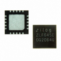
ZLF645E0Q2064G Zilog, ZLF645E0Q2064G Datasheet - Page 140

ZLF645E0Q2064G
Manufacturer Part Number
ZLF645E0Q2064G
Description
IC MCU 64K FLASH 1K RAM 20-QFN
Manufacturer
Zilog
Series
Crimzon™ ZLFr
Specifications of ZLF645E0Q2064G
Core Processor
Z8 LXMC
Core Size
8-Bit
Speed
8MHz
Connectivity
UART/USART
Peripherals
Brown-out Detect/Reset, HLVD, POR, WDT
Number Of I /o
16
Program Memory Size
64KB (64K x 8)
Program Memory Type
FLASH
Ram Size
1K x 8
Voltage - Supply (vcc/vdd)
1.9 V ~ 3.6 V
Operating Temperature
0°C ~ 70°C
Package / Case
20-VQFN Exposed Pad, 20-HVQFN, 20-SQFN, 20-DHVQFN
Lead Free Status / RoHS Status
Lead free / RoHS Compliant
Eeprom Size
-
Data Converters
-
Oscillator Type
-
Other names
269-4723
Available stocks
Company
Part Number
Manufacturer
Quantity
Price
Company:
Part Number:
ZLF645E0Q2064G
Manufacturer:
Maxim
Quantity:
28
- Current page: 140 of 197
- Download datasheet (3Mb)
Reset and Power Management
PS026407-0408
Table 67. Reset and Power Management Registers
12-Bit
D0C
F0A
F0B
F0C
F0D
Note:
Address (Hex)
Bank 8-Bit
D
F
F
F
F
The ZLF645 MCU provides the following reduced-power modes, power monitoring, and
reset features:
•
•
•
•
•
•
•
For supply current values under various conditions, see
Figure 43
registers for reset and power management features. Some features are affected by registers
described in other chapters.
0C
0A
0B
0C
0D
Voltage Brownout Standby—Stops the oscillator and internal clock when the power
level drops below the VBO low voltage detect point. Initiates a power-on reset when
power is restored above the VBO detect point.
STOP Mode—Stops the clock and oscillator, reduces the MCU supply current to a
very low level until a power-on reset or Stop Mode Recovery occurs.
HALT Mode—Stops the internal clock to the CPU until an enabled interrupt request
is received.
Voltage Detection—Optionally sets a flag if a low- or high-voltage condition occurs.
The low-voltage detection flag can generate an interrupt request, if enabled.
Power-On Reset—Starts the oscillator and internal clock, and initializes the system to
its power-on reset defaults.
Watchdog Timer—Optionally generates a Power-On Reset if the program fails to
execute the WDT instruction within a specified time interval.
Stop Mode Recovery—Restarts the oscillator and internal clock, and initializes most
of the system to its power-on reset defaults. Some register values are not reset by a
Stop Mode Recovery.
on page 133 displays the Power-On Reset sources.
Register Description
Low-Voltage Detection Register
Stop Mode Recovery Register 4
Stop Mode Recovery Register
Stop Mode Recovery Register 1
Stop Mode Recovery Register 2
Mnemonic
LVD
SMR4
SMR
SMR1
SMR2
DC Characteristics on page
ZLF645 Series Flash MCUs
Table 67
Reset and Power Management
Product Specification
Reset
1 1 1 1 _100 0 b
XXX0 _000 0 b
0 0 1 0 _00 0 0 b
00h
X0 X0 _00XXb
lists control
Page No
135
151
141
145
147
160.
132
Related parts for ZLF645E0Q2064G
Image
Part Number
Description
Manufacturer
Datasheet
Request
R

Part Number:
Description:
Microcontrollers (MCU) Zlf645 (32K 20L Ssop F645 (32K 20L Ssop )
Manufacturer:
Maxim Integrated Products

Part Number:
Description:
Microcontrollers (MCU) Crimzon Flash Infrared MCU
Manufacturer:
Maxim Integrated Products

Part Number:
Description:
Microcontrollers (MCU) Crimzon Flash Infrared MCU
Manufacturer:
Maxim Integrated Products

Part Number:
Description:
Microcontrollers (MCU) Crimzon Flash Infrared MCU
Manufacturer:
Maxim Integrated Products

Part Number:
Description:
Microcontrollers (MCU) Crimzon Flash Infrared MCU
Manufacturer:
Maxim Integrated Products

Part Number:
Description:
Microcontrollers (MCU) Crimzon Flash Infrared MCU
Manufacturer:
Maxim Integrated Products

Part Number:
Description:
Microcontrollers (MCU) Crimzon Flash Infrared MCU
Manufacturer:
Maxim Integrated Products

Part Number:
Description:
Microcontrollers (MCU) Crimzon Flash Infrared MCU
Manufacturer:
Maxim Integrated Products

Part Number:
Description:
Microcontrollers (MCU) Crimzon Flash Infrared MCU
Manufacturer:
Maxim Integrated Products

Part Number:
Description:
Microcontrollers (MCU) Crimzon Flash Infrared MCU
Manufacturer:
Maxim Integrated Products

Part Number:
Description:
Microcontrollers (MCU) Crimzon Flash Infrared MCU
Manufacturer:
Maxim Integrated Products

Part Number:
Description:
Microcontrollers (MCU) Crimzon Flash Infrared MCU
Manufacturer:
Maxim Integrated Products

Part Number:
Description:
Microcontrollers (MCU) Crimzon Flash Infrared MCU
Manufacturer:
Maxim Integrated Products

Part Number:
Description:
Microcontrollers (MCU) Crimzon Flash Infrared MCU
Manufacturer:
Maxim Integrated Products

Part Number:
Description:
Microcontrollers (MCU) Crimzon Flash Infrared MCU
Manufacturer:
Maxim Integrated Products


