C8051F320DK Silicon Laboratories Inc, C8051F320DK Datasheet - Page 209
C8051F320DK
Manufacturer Part Number
C8051F320DK
Description
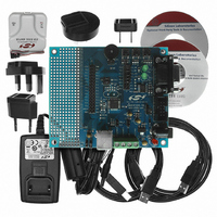
DEV KIT FOR C8051F320/F321
Manufacturer
Silicon Laboratories Inc
Type
MCUr
Specifications of C8051F320DK
Contents
Evaluation Board, Power Supply, USB Cables, Adapter and Documentation
Processor To Be Evaluated
C8051F320/F321
Interface Type
USB
Silicon Manufacturer
Silicon Labs
Core Architecture
8051
Silicon Core Number
C8051F320
Silicon Family Name
C8051F32x
Lead Free Status / RoHS Status
Contains lead / RoHS non-compliant
For Use With/related Products
Silicon Laboratories C8051F320, C8051F321
Lead Free Status / Rohs Status
Lead free / RoHS Compliant
Other names
336-1260
Available stocks
Company
Part Number
Manufacturer
Quantity
Price
Company:

Part Number:
C8051F320DK
Manufacturer:
SiliconL
Quantity:
4


19. Timers
Each MCU includes four counter/timers: two are 16-bit counter/timers compatible with those found in the
standard 8051, and two are 16-bit auto-reload timer for use with the ADC, SMBus, USB (frame measure-
ments), or for general purpose use. These timers can be used to measure time intervals, count external
events and generate periodic interrupt requests. Timer 0 and Timer 1 are nearly identical and have four pri-
mary modes of operation. Timer 2 and Timer 3 offer 16-bit and split 8-bit timer functionality with auto-
reload.
Timers 0 and 1 may be clocked by one of five sources, determined by the Timer Mode Select bits (T1M-
T0M) and the Clock Scale bits (SCA1-SCA0). The Clock Scale bits define a pre-scaled clock from which
Timer 0 and/or Timer 1 may be clocked (See Figure 19.3 for pre-scaled clock selection).
Timer 0/1 may then be configured to use this pre-scaled clock signal or the system clock. Timer 2 and
Timer 3 may be clocked by the system clock, the system clock divided by 12, or the external oscillator
clock source divided by 8.
Timer 0 and Timer 1 may also be operated as counters. When functioning as a counter, a counter/timer
register is incremented on each high-to-low transition at the selected input pin (T0 or T1). Events with a fre-
quency of up to one-fourth the system clock's frequency can be counted. The input signal need not be peri-
odic, but it should be held at a given level for at least two full system clock cycles to ensure the level is
properly sampled.
19.1. Timer 0 and Timer 1
Each timer is implemented as a 16-bit register accessed as two separate bytes: a low byte (TL0 or TL1)
and a high byte (TH0 or TH1). The Counter/Timer Control register (TCON) is used to enable Timer 0 and
Timer 1 as well as indicate status. Timer 0 interrupts can be enabled by setting the ET0 bit in the IE register
(Section “9.3.5. Interrupt Register Descriptions” on page 90); Timer 1 interrupts can be enabled by setting
the ET1 bit in the IE register (SFR Definition 9.7). Both counter/timers operate in one of four primary
modes selected by setting the Mode Select bits T1M1-T0M0 in the Counter/Timer Mode register (TMOD).
Each timer can be configured independently. Each operating mode is described below.
19.1.1. Mode 0: 13-bit Counter/Timer
Timer 0 and Timer 1 operate as 13-bit counter/timers in Mode 0. The following describes the configuration
and operation of Timer 0. However, both timers operate identically, and Timer 1 is configured in the same
manner as described for Timer 0.
The TH0 register holds the eight MSBs of the 13-bit counter/timer. TL0 holds the five LSBs in bit positions
TL0.4-TL0.0. The three upper bits of TL0 (TL0.7-TL0.5) are indeterminate and should be masked out or
ignored when reading. As the 13-bit timer register increments and overflows from 0x1FFF (all ones) to
0x0000, the timer overflow flag TF0 (TCON.5) is set and an interrupt will occur if Timer 0 interrupts are
enabled.
The C/T0 bit (TMOD.2) selects the counter/timer's clock source. When C/T0 is set to logic 1, high-to-low
transitions at the selected Timer 0 input pin (T0) increment the timer register (Refer to Section
Two 8-bit counter/timers (Timer 0 only)
8-bit counter/timer with auto-reload
Timer 0 and Timer 1 Modes:
13-bit counter/timer
16-bit counter/timer
16-bit timer with auto-reload
Two 8-bit timers with
Timer 2 Modes:
Rev. 1.4
auto-reload
16-bit timer with auto-reload
C8051F320/1
Two 8-bit timers with
Timer 3 Modes:
auto-reload
209
Related parts for C8051F320DK
Image
Part Number
Description
Manufacturer
Datasheet
Request
R

Part Number:
Description:
SMD/C°/SINGLE-ENDED OUTPUT SILICON OSCILLATOR
Manufacturer:
Silicon Laboratories Inc
Part Number:
Description:
Manufacturer:
Silicon Laboratories Inc
Datasheet:
Part Number:
Description:
N/A N/A/SI4010 AES KEYFOB DEMO WITH LCD RX
Manufacturer:
Silicon Laboratories Inc
Datasheet:
Part Number:
Description:
N/A N/A/SI4010 SIMPLIFIED KEY FOB DEMO WITH LED RX
Manufacturer:
Silicon Laboratories Inc
Datasheet:
Part Number:
Description:
N/A/-40 TO 85 OC/EZLINK MODULE; F930/4432 HIGH BAND (REV E/B1)
Manufacturer:
Silicon Laboratories Inc
Part Number:
Description:
EZLink Module; F930/4432 Low Band (rev e/B1)
Manufacturer:
Silicon Laboratories Inc
Part Number:
Description:
I°/4460 10 DBM RADIO TEST CARD 434 MHZ
Manufacturer:
Silicon Laboratories Inc
Part Number:
Description:
I°/4461 14 DBM RADIO TEST CARD 868 MHZ
Manufacturer:
Silicon Laboratories Inc
Part Number:
Description:
I°/4463 20 DBM RFSWITCH RADIO TEST CARD 460 MHZ
Manufacturer:
Silicon Laboratories Inc
Part Number:
Description:
I°/4463 20 DBM RADIO TEST CARD 868 MHZ
Manufacturer:
Silicon Laboratories Inc
Part Number:
Description:
I°/4463 27 DBM RADIO TEST CARD 868 MHZ
Manufacturer:
Silicon Laboratories Inc
Part Number:
Description:
I°/4463 SKYWORKS 30 DBM RADIO TEST CARD 915 MHZ
Manufacturer:
Silicon Laboratories Inc
Part Number:
Description:
N/A N/A/-40 TO 85 OC/4463 RFMD 30 DBM RADIO TEST CARD 915 MHZ
Manufacturer:
Silicon Laboratories Inc
Part Number:
Description:
I°/4463 20 DBM RADIO TEST CARD 169 MHZ
Manufacturer:
Silicon Laboratories Inc