C8051F320DK Silicon Laboratories Inc, C8051F320DK Datasheet - Page 117
C8051F320DK
Manufacturer Part Number
C8051F320DK
Description
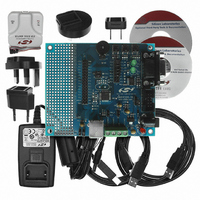
DEV KIT FOR C8051F320/F321
Manufacturer
Silicon Laboratories Inc
Type
MCUr
Specifications of C8051F320DK
Contents
Evaluation Board, Power Supply, USB Cables, Adapter and Documentation
Processor To Be Evaluated
C8051F320/F321
Interface Type
USB
Silicon Manufacturer
Silicon Labs
Core Architecture
8051
Silicon Core Number
C8051F320
Silicon Family Name
C8051F32x
Lead Free Status / RoHS Status
Contains lead / RoHS non-compliant
For Use With/related Products
Silicon Laboratories C8051F320, C8051F321
Lead Free Status / Rohs Status
Lead free / RoHS Compliant
Other names
336-1260
Available stocks
Company
Part Number
Manufacturer
Quantity
Price
Company:

Part Number:
C8051F320DK
Manufacturer:
SiliconL
Quantity:
4


On C8051F320/1 devices, OSCICL is factory calibrated to obtain a 12 MHz base frequency (f
tion 13.1.1 details oscillator programming for C8051F320/1 devices. Electrical specifications for the preci-
sion internal oscillator are given in Table 13.3 on page 125. Note that the system clock may be derived
from the programmed internal oscillator divided by 1, 2, 4, or 8, as defined by the IFCN bits in register
OSCICN. The divide value defaults to 8 following a reset.
13.1.1. Programming the Internal Oscillator on C8051F320/1 Devices
The OSCICL reset value is factory calibrated to result in a 12 MHz internal oscillator with a ±1.5% accu-
racy; this frequency is suitable for use as the USB clock (see Section 13.4). Software may modify the fre-
quency of the internal oscillator as described below.
Important Note: Once the internal oscillator frequency has been modified, the internal oscillator may not
be used as the USB clock as described in Section 13.4. The internal oscillator frequency will reset to its
original factory-calibrated frequency following any device reset, at which point the oscillator is suitable for
use as the USB clock.
Software should read and adjust the value of OSCICL according to Equation 13.1 to obtain the desired fre-
quency. The example below shows how to obtain an 11.6 MHz internal oscillator frequency.
f
f
The required change in period (T
Using Equation 13.1 and the above calculations, find OSCICL:
OSCICL is rounded to the nearest integer (14) and added to the reset value of register OSCICL.
T
BASE
DES
OSCICL
f
T
2.87 10
BASE
BASE
DES
is the desired internal oscillator frequency; T
Equation 13.1. Typical Change in Internal Oscillator Period with OSCICL
is the internal oscillator reset frequency; T
=
=
=
12000000Hz
----------------------- - s
12000000
9 –
----------------------- -
11600000
=
=
1
13.79
1
0.0025
–
----------------------- -
12000000
------------ -
f
BASE
1
1
T 0.0025
DES
OSCICL
) is the difference between the base period and the desired period.
=
2.87
BASE
Rev. 1.4
DES
10
------------ -
f
T
f
BASE
DES
DES
1
9 –
is the reset oscillator period.
is the desired oscillator period.
s
=
=
OSCICL
11600000Hz
----------------------- - s
11600000
1
C8051F320/1
BASE
). Sec-
117
Related parts for C8051F320DK
Image
Part Number
Description
Manufacturer
Datasheet
Request
R

Part Number:
Description:
SMD/C°/SINGLE-ENDED OUTPUT SILICON OSCILLATOR
Manufacturer:
Silicon Laboratories Inc
Part Number:
Description:
Manufacturer:
Silicon Laboratories Inc
Datasheet:
Part Number:
Description:
N/A N/A/SI4010 AES KEYFOB DEMO WITH LCD RX
Manufacturer:
Silicon Laboratories Inc
Datasheet:
Part Number:
Description:
N/A N/A/SI4010 SIMPLIFIED KEY FOB DEMO WITH LED RX
Manufacturer:
Silicon Laboratories Inc
Datasheet:
Part Number:
Description:
N/A/-40 TO 85 OC/EZLINK MODULE; F930/4432 HIGH BAND (REV E/B1)
Manufacturer:
Silicon Laboratories Inc
Part Number:
Description:
EZLink Module; F930/4432 Low Band (rev e/B1)
Manufacturer:
Silicon Laboratories Inc
Part Number:
Description:
I°/4460 10 DBM RADIO TEST CARD 434 MHZ
Manufacturer:
Silicon Laboratories Inc
Part Number:
Description:
I°/4461 14 DBM RADIO TEST CARD 868 MHZ
Manufacturer:
Silicon Laboratories Inc
Part Number:
Description:
I°/4463 20 DBM RFSWITCH RADIO TEST CARD 460 MHZ
Manufacturer:
Silicon Laboratories Inc
Part Number:
Description:
I°/4463 20 DBM RADIO TEST CARD 868 MHZ
Manufacturer:
Silicon Laboratories Inc
Part Number:
Description:
I°/4463 27 DBM RADIO TEST CARD 868 MHZ
Manufacturer:
Silicon Laboratories Inc
Part Number:
Description:
I°/4463 SKYWORKS 30 DBM RADIO TEST CARD 915 MHZ
Manufacturer:
Silicon Laboratories Inc
Part Number:
Description:
N/A N/A/-40 TO 85 OC/4463 RFMD 30 DBM RADIO TEST CARD 915 MHZ
Manufacturer:
Silicon Laboratories Inc
Part Number:
Description:
I°/4463 20 DBM RADIO TEST CARD 169 MHZ
Manufacturer:
Silicon Laboratories Inc