C8051F320DK Silicon Laboratories Inc, C8051F320DK Datasheet - Page 150
C8051F320DK
Manufacturer Part Number
C8051F320DK
Description
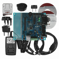
DEV KIT FOR C8051F320/F321
Manufacturer
Silicon Laboratories Inc
Type
MCUr
Specifications of C8051F320DK
Contents
Evaluation Board, Power Supply, USB Cables, Adapter and Documentation
Processor To Be Evaluated
C8051F320/F321
Interface Type
USB
Silicon Manufacturer
Silicon Labs
Core Architecture
8051
Silicon Core Number
C8051F320
Silicon Family Name
C8051F32x
Lead Free Status / RoHS Status
Contains lead / RoHS non-compliant
For Use With/related Products
Silicon Laboratories C8051F320, C8051F321
Lead Free Status / Rohs Status
Lead free / RoHS Compliant
Other names
336-1260
Available stocks
Company
Part Number
Manufacturer
Quantity
Price
Company:

Part Number:
C8051F320DK
Manufacturer:
SiliconL
Quantity:
4


C8051F320/1
disabling appropriate peripherals and/or configuring clock sources for low power modes. See Section
“13. Oscillators” on page 116 for more details on internal oscillator configuration, including the Suspend
mode feature of the internal oscillator.
USB0 exits Suspend mode when any of the following occur: (1) Resume signaling is detected or gener-
ated, (2) Reset signaling is detected, or (3) a device or USB reset occurs. If suspended, the internal oscil-
lator will exit Suspend mode upon any of the above listed events.
Resume Signaling: USB0 will exit Suspend mode if Resume signaling is detected on the bus. A Resume
interrupt will be generated upon detection if enabled (RESINTE = ‘1’). Software may force a Remote
Wakeup by writing ‘1’ to the RESUME bit (POWER.2). When forcing a Remote Wakeup, software should
write RESUME = ‘0’ to end Resume signaling 10-15 ms after the Remote Wakeup is initiated (RESUME =
‘1’).
ISO Update: When software writes ‘1’ to the ISOUP bit (POWER.7), the ISO Update function is enabled.
With ISO Update enabled, new packets written to an ISO IN endpoint will not be transmitted until a new
Start-Of-Frame (SOF) is received. If the ISO IN endpoint receives an IN token before a SOF, USB0 will
transmit a zero-length packet. When ISOUP = ‘1’, ISO Update is enabled for all ISO endpoints.
USB Enable: USB0 is disabled following a Power-On-Reset (POR). USB0 is enabled by clearing the
USBINH bit (POWER.4). Once written to ‘0’, the USBINH can only be set to ‘1’ by one of the following: (1)
a Power-On-Reset (POR), or (2) an asynchronous USB0 reset generated by writing ‘1’ to the USBRST bit
(POWER.3).
Software should perform all USB0 configuration before enabling USB0. The configuration sequence
should be performed as follows:
150
Step 1. Select and enable the USB clock source.
Step 2. Reset USB0 by writing USBRST= ‘1’.
Step 3. Configure and enable the USB Transceiver.
Step 4. Perform any USB0 function configuration (interrupts, Suspend detect).
Step 5. Enable USB0 by writing USBINH = ‘0’.
Rev. 1.4
Related parts for C8051F320DK
Image
Part Number
Description
Manufacturer
Datasheet
Request
R

Part Number:
Description:
SMD/C°/SINGLE-ENDED OUTPUT SILICON OSCILLATOR
Manufacturer:
Silicon Laboratories Inc
Part Number:
Description:
Manufacturer:
Silicon Laboratories Inc
Datasheet:
Part Number:
Description:
N/A N/A/SI4010 AES KEYFOB DEMO WITH LCD RX
Manufacturer:
Silicon Laboratories Inc
Datasheet:
Part Number:
Description:
N/A N/A/SI4010 SIMPLIFIED KEY FOB DEMO WITH LED RX
Manufacturer:
Silicon Laboratories Inc
Datasheet:
Part Number:
Description:
N/A/-40 TO 85 OC/EZLINK MODULE; F930/4432 HIGH BAND (REV E/B1)
Manufacturer:
Silicon Laboratories Inc
Part Number:
Description:
EZLink Module; F930/4432 Low Band (rev e/B1)
Manufacturer:
Silicon Laboratories Inc
Part Number:
Description:
I°/4460 10 DBM RADIO TEST CARD 434 MHZ
Manufacturer:
Silicon Laboratories Inc
Part Number:
Description:
I°/4461 14 DBM RADIO TEST CARD 868 MHZ
Manufacturer:
Silicon Laboratories Inc
Part Number:
Description:
I°/4463 20 DBM RFSWITCH RADIO TEST CARD 460 MHZ
Manufacturer:
Silicon Laboratories Inc
Part Number:
Description:
I°/4463 20 DBM RADIO TEST CARD 868 MHZ
Manufacturer:
Silicon Laboratories Inc
Part Number:
Description:
I°/4463 27 DBM RADIO TEST CARD 868 MHZ
Manufacturer:
Silicon Laboratories Inc
Part Number:
Description:
I°/4463 SKYWORKS 30 DBM RADIO TEST CARD 915 MHZ
Manufacturer:
Silicon Laboratories Inc
Part Number:
Description:
N/A N/A/-40 TO 85 OC/4463 RFMD 30 DBM RADIO TEST CARD 915 MHZ
Manufacturer:
Silicon Laboratories Inc
Part Number:
Description:
I°/4463 20 DBM RADIO TEST CARD 169 MHZ
Manufacturer:
Silicon Laboratories Inc