STEVAL-IFS003V1 STMicroelectronics, STEVAL-IFS003V1 Datasheet - Page 99
STEVAL-IFS003V1
Manufacturer Part Number
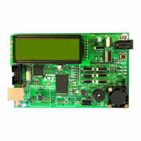
STEVAL-IFS003V1
Description
BOARD STLM75/STDS75/ST72F651
Manufacturer
STMicroelectronics
Datasheets
1.STLM75DS2F.pdf
(40 pages)
2.STDS75M2F.pdf
(39 pages)
3.STEVAL-IFS003V1.pdf
(161 pages)
4.STEVAL-IFS003V1.pdf
(4 pages)
Specifications of STEVAL-IFS003V1
Design Resources
STEVAL-IFS003V1 Gerber Files STEVAL-IFS003V1 Schematic STEVAL-IFS003V1 Bill of Materials
Sensor Type
Temperature
Sensing Range
-55°C ~ 125°C
Interface
I²C
Voltage - Supply
7.5 V ~ 19 V
Embedded
Yes, MCU, 8-Bit
Utilized Ic / Part
ST72F651, STDS75, STLM75
Silicon Manufacturer
ST Micro
Silicon Core Number
STLM75/STDS75 And ST72F651AR6
Kit Application Type
Sensing - Temperature
Application Sub Type
Temperature Sensor
Kit Contents
Board
Lead Free Status / RoHS Status
Lead free / RoHS Compliant
Sensitivity
-
Lead Free Status / Rohs Status
Lead free / RoHS Compliant
Other names
497-6238


SERIAL PERIPHERAL INTERFACE (Cont’d)
11.6.5 Error Flags
11.6.5.1 Master Mode Fault (MODF)
Master mode fault occurs when the master device
has its SS pin pulled low.
When a Master mode fault occurs:
Clearing the MODF bit is done through a software
sequence:
1. A read access to the SPICSR register while the
2. A write to the SPICR register.
Notes: To avoid any conflicts in an application
with multiple slaves, the SS pin must be pulled
high during the MODF bit clearing sequence. The
SPE and MSTR bits may be restored to their orig-
inal state during or after this clearing sequence.
Hardware does not allow the user to set the SPE
and MSTR bits while the MODF bit is set except in
the MODF bit clearing sequence.
In a slave device, the MODF bit can not be set, but
in a multimaster configuration the device can be in
slave mode with the MODF bit set.
The MODF bit indicates that there might have
been a multimaster conflict and allows software to
handle this using an interrupt routine and either
perform to a reset or return to an application de-
fault state.
Figure 60. Clearing the WCOL bit (Write Collision Flag) Software Sequence
1st Step
2nd Step
– The MODF bit is set and an SPI interrupt re-
– The SPE bit is reset. This blocks all output
– The MSTR bit is reset, thus forcing the device
quest is generated if the SPIE bit is set.
from the device and disables the SPI periph-
eral.
into slave mode.
MODF bit is set.
Clearing sequence after SPIF = 1 (end of a data byte transfer)
Clearing sequence before SPIF = 1 (during a data byte transfer)
1st Step
2nd Step
Read SPICSR
Read SPIDR
RESULT
SPIF =0
WCOL=0
Read SPIDR
Read SPICSR
Doc ID 7215 Rev 4
RESULT
WCOL=0
11.6.5.2 Overrun Condition (OVR)
An overrun condition occurs, when the master de-
vice has sent a data byte and the slave device has
not cleared the SPIF bit issued from the previously
transmitted byte.
When an Overrun occurs:
– The OVR bit is set and an interrupt request is
In this case, the receiver buffer contains the byte
sent after the SPIF bit was last cleared. A read to
the SPIDR register returns this byte. All other
bytes are lost.
The OVR bit is cleared by reading the SPICSR
register.
11.6.5.3 Write Collision Error (WCOL)
A write collision occurs when the software tries to
write to the SPIDR register while a data transfer is
taking place with an external device. When this
happens, the transfer continues uninterrupted;
and the software write will be unsuccessful.
Write collisions can occur both in master and slave
mode. See also
Management.
Note: a "read collision" will never occur since the
received data byte is placed in a buffer in which
access is always synchronous with the MCU oper-
ation.
The WCOL bit in the SPICSR register is set if a
write collision occurs.
No SPI interrupt is generated when the WCOL bit
is set (the WCOL bit is a status flag only).
Clearing the WCOL bit is done through a software
sequence (see
generated if the SPIE bit is set.
Note: Writing to the SPIDR regis-
ter instead of reading it does not
reset the WCOL bit
Figure
Section 11.6.3.2 Slave Select
60).
ST72651AR6
99/161
Related parts for STEVAL-IFS003V1
Image
Part Number
Description
Manufacturer
Datasheet
Request
R

Part Number:
Description:
BOARD EVAL SPZB260 MOD FOR STR9
Manufacturer:
STMicroelectronics
Datasheet:

Part Number:
Description:
BOARD EVAL EXTENSION SN250
Manufacturer:
STMicroelectronics
Datasheet:

Part Number:
Description:
BOARD EVAL AB-54003L-512
Manufacturer:
STMicroelectronics
Datasheet:

Part Number:
Description:
BOARD REF DESIGN RF DMOS PWR AMP
Manufacturer:
STMicroelectronics
Datasheet:

Part Number:
Description:
BOARD EVAL PWR AMP AB-84008L-470
Manufacturer:
STMicroelectronics
Datasheet:

Part Number:
Description:
BOARD EVAL FOR STM32F103XX
Manufacturer:
STMicroelectronics
Datasheet:

Part Number:
Description:
BOARD EVAL AB-54003L-512
Manufacturer:
STMicroelectronics
Datasheet:

Part Number:
Description:
BOARD SMART PLUG STM32 SPZB260PR
Manufacturer:
STMicroelectronics
Datasheet:

Part Number:
Description:
BOARD DEMO BLUETOOTH SPBT2532C2
Manufacturer:
STMicroelectronics
Datasheet:
Part Number:
Description:
ZIGBEE USB DONGLE EVAL KIT
Manufacturer:
STMicroelectronics
Datasheet:
Part Number:
Description:
STMicroelectronics [RIPPLE-CARRY BINARY COUNTER/DIVIDERS]
Manufacturer:
STMicroelectronics
Datasheet:
Part Number:
Description:
STMicroelectronics [LIQUID-CRYSTAL DISPLAY DRIVERS]
Manufacturer:
STMicroelectronics
Datasheet:

Part Number:
Description:
BOARD EVAL FOR MEMS SENSORS
Manufacturer:
STMicroelectronics
Datasheet: