STEVAL-IFS003V1 STMicroelectronics, STEVAL-IFS003V1 Datasheet - Page 26
STEVAL-IFS003V1
Manufacturer Part Number
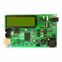
STEVAL-IFS003V1
Description
BOARD STLM75/STDS75/ST72F651
Manufacturer
STMicroelectronics
Datasheets
1.STLM75DS2F.pdf
(40 pages)
2.STDS75M2F.pdf
(39 pages)
3.STEVAL-IFS003V1.pdf
(161 pages)
4.STEVAL-IFS003V1.pdf
(4 pages)
Specifications of STEVAL-IFS003V1
Design Resources
STEVAL-IFS003V1 Gerber Files STEVAL-IFS003V1 Schematic STEVAL-IFS003V1 Bill of Materials
Sensor Type
Temperature
Sensing Range
-55°C ~ 125°C
Interface
I²C
Voltage - Supply
7.5 V ~ 19 V
Embedded
Yes, MCU, 8-Bit
Utilized Ic / Part
ST72F651, STDS75, STLM75
Silicon Manufacturer
ST Micro
Silicon Core Number
STLM75/STDS75 And ST72F651AR6
Kit Application Type
Sensing - Temperature
Application Sub Type
Temperature Sensor
Kit Contents
Board
Lead Free Status / RoHS Status
Lead free / RoHS Compliant
Sensitivity
-
Lead Free Status / Rohs Status
Lead free / RoHS Compliant
Other names
497-6238


ST72651AR6
6 SUPPLY, RESET AND CLOCK MANAGEMENT
6.1 CLOCK SYSTEM
6.1.1 General Description
The MCU accepts either a 12 MHz crystal or an
external clock signal to drive the internal oscillator.
The internal clock (f
nal oscillator frequency (f
Stand-alone mode and 48Mhz in USB mode.
The internal clock (f
ing the CP[1:0] and CPEN bits in the MISCR1 reg-
ister.
In USBV
generating a 48MHz clock to the USB. In this
mode, f
In V
bled, and the maximum frequency of f
MHz.
The internal clock signal (f
the on-chip peripherals. The CPU clock signal
consists of a square wave with a duty cycle of
50%.
The internal oscillator is designed to operate with
an AT-cut parallel resonant quartz in the frequency
range specified for f
ure 16
Table 7
crystal and associated components should be
mounted as close as possible to the input pins in
order to minimize output distortion and start-up
stabilisation time.
Table 7. Recommended Values for 12-MHz
Crystal Resonator
Note: R
crystal (see crystal specification).
26/161
1
C
C
R
OSCOUT
DD
OSCIN
SMAX
is recommended when using a crystal, and
mode the PLL and the USB clock are disa-
CPU
SMAX
lists the recommended capacitance. The
DD
power supply mode, the PLL is active,
can be configured to be up to 8 MHz.
is the equivalent serial resistor of the
56pF
56pF
20 Ω
CPU
CPU
osc
. The circuit shown in
) is software selectable us-
) is derived from the inter-
OSC
CPU
47pF
47pF
25 Ω
), which is 12 Mhz in
) is also routed to
CPU
22pF
22pF
70 Ω
Doc ID 7215 Rev 4
is 6
Fig-
6.1.2 External Clock
An external clock may be applied to the OSCIN in-
put with the OSCOUT pin not connected, as
shown on
does not apply when using an external clock input.
The equivalent specification of the external clock
source should be used instead of t
tion 6.5 CONTROL TIMING).
Figure 15. External Clock Source Connections
Figure 16. Crystal Resonator
C
OSCIN
Figure
OSCIN
EXTERNAL
CLOCK
OSCIN
15. The t
OSCOUT
OSCOUT
OXOV
NC
C
OSCOUT
OXOV
specifications
(see Sec-
Related parts for STEVAL-IFS003V1
Image
Part Number
Description
Manufacturer
Datasheet
Request
R

Part Number:
Description:
BOARD EVAL SPZB260 MOD FOR STR9
Manufacturer:
STMicroelectronics
Datasheet:

Part Number:
Description:
BOARD EVAL EXTENSION SN250
Manufacturer:
STMicroelectronics
Datasheet:

Part Number:
Description:
BOARD EVAL AB-54003L-512
Manufacturer:
STMicroelectronics
Datasheet:

Part Number:
Description:
BOARD REF DESIGN RF DMOS PWR AMP
Manufacturer:
STMicroelectronics
Datasheet:

Part Number:
Description:
BOARD EVAL PWR AMP AB-84008L-470
Manufacturer:
STMicroelectronics
Datasheet:

Part Number:
Description:
BOARD EVAL FOR STM32F103XX
Manufacturer:
STMicroelectronics
Datasheet:

Part Number:
Description:
BOARD EVAL AB-54003L-512
Manufacturer:
STMicroelectronics
Datasheet:

Part Number:
Description:
BOARD SMART PLUG STM32 SPZB260PR
Manufacturer:
STMicroelectronics
Datasheet:

Part Number:
Description:
BOARD DEMO BLUETOOTH SPBT2532C2
Manufacturer:
STMicroelectronics
Datasheet:
Part Number:
Description:
ZIGBEE USB DONGLE EVAL KIT
Manufacturer:
STMicroelectronics
Datasheet:
Part Number:
Description:
STMicroelectronics [RIPPLE-CARRY BINARY COUNTER/DIVIDERS]
Manufacturer:
STMicroelectronics
Datasheet:
Part Number:
Description:
STMicroelectronics [LIQUID-CRYSTAL DISPLAY DRIVERS]
Manufacturer:
STMicroelectronics
Datasheet:

Part Number:
Description:
BOARD EVAL FOR MEMS SENSORS
Manufacturer:
STMicroelectronics
Datasheet: