STEVAL-IFS003V1 STMicroelectronics, STEVAL-IFS003V1 Datasheet - Page 94
STEVAL-IFS003V1
Manufacturer Part Number
STEVAL-IFS003V1
Description
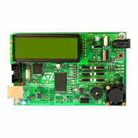
BOARD STLM75/STDS75/ST72F651
Manufacturer
STMicroelectronics
Datasheets
1.STLM75DS2F.pdf
(40 pages)
2.STDS75M2F.pdf
(39 pages)
3.STEVAL-IFS003V1.pdf
(161 pages)
4.STEVAL-IFS003V1.pdf
(4 pages)
Specifications of STEVAL-IFS003V1
Design Resources
STEVAL-IFS003V1 Gerber Files STEVAL-IFS003V1 Schematic STEVAL-IFS003V1 Bill of Materials
Sensor Type
Temperature
Sensing Range
-55°C ~ 125°C
Interface
I²C
Voltage - Supply
7.5 V ~ 19 V
Embedded
Yes, MCU, 8-Bit
Utilized Ic / Part
ST72F651, STDS75, STLM75
Silicon Manufacturer
ST Micro
Silicon Core Number
STLM75/STDS75 And ST72F651AR6
Kit Application Type
Sensing - Temperature
Application Sub Type
Temperature Sensor
Kit Contents
Board
Lead Free Status / RoHS Status
Lead free / RoHS Compliant
Sensitivity
-
Lead Free Status / Rohs Status
Lead free / RoHS Compliant
Other names
497-6238


ST72651AR6
11.6 SERIAL PERIPHERAL INTERFACE (SPI)
11.6.1 Introduction
The Serial Peripheral Interface (SPI) allows full-
duplex, synchronous, serial communication with
external devices. An SPI system may consist of a
master and one or more slaves however the SPI
interface can not be a master in a multimaster sys-
tem.
11.6.2 Main Features
■
■
■
■
■
■
■
■
■
Note: In slave mode, continuous transmission is
not possible at maximum frequency due to the
Figure 55. Serial Peripheral Interface Block Diagram
94/161
Full duplex synchronous transfers (on 3 lines)
Simplex synchronous transfers (on 2 lines)
Master or slave operation
Six master mode frequencies (f
f
SS Management by software or hardware
Programmable clock polarity and phase
End of transfer interrupt flag
Write collision, Master Mode Fault and Overrun
flags
MOSI
MISO
CPU
SCK
SS
/2 max. slave mode frequency (see note)
SOD
bit
SPIDR
8-Bit Shift Register
Read Buffer
SERIAL CLOCK
CPU
GENERATOR
CONTROL
MASTER
/2 max.)
Data/Address Bus
Read
Write
Doc ID 7215 Rev 4
software overhead for clearing status flags and to
initiate the next transmission sequence.
11.6.3 General Description
Figure 55
(SPI) block diagram. There are 3 registers:
The SPI is connected to external devices through
3 pins:
– SPI Control Register (SPICR)
– SPI Control/Status Register (SPICSR)
– SPI Data Register (SPIDR)
– MISO: Master In / Slave Out data
– MOSI: Master Out / Slave In data
– SCK: Serial Clock out by SPI masters and in-
– SS: Slave select:
put by SPI slaves
This input signal acts as a ‘chip select’ to let
the SPI master communicate with slaves indi-
vidually and to avoid contention on the data
lines. Slave SS inputs can be driven by stand-
ard I/O ports on the master MCU.
7
SPIE
SPIF WCOL
7
SPE
shows the serial peripheral interface
CONTROL
SPR2
OVR
STATE
SPI
Interrupt
request
MODF
MSTR
CPOL
0
CPHA
SOD
SS
SPICR
SPICSR
SSM
SPR1
0
1
SPR0
SSI
0
0
Related parts for STEVAL-IFS003V1
Image
Part Number
Description
Manufacturer
Datasheet
Request
R

Part Number:
Description:
BOARD EVAL SPZB260 MOD FOR STR9
Manufacturer:
STMicroelectronics
Datasheet:

Part Number:
Description:
BOARD EVAL EXTENSION SN250
Manufacturer:
STMicroelectronics
Datasheet:

Part Number:
Description:
BOARD EVAL AB-54003L-512
Manufacturer:
STMicroelectronics
Datasheet:

Part Number:
Description:
BOARD REF DESIGN RF DMOS PWR AMP
Manufacturer:
STMicroelectronics
Datasheet:

Part Number:
Description:
BOARD EVAL PWR AMP AB-84008L-470
Manufacturer:
STMicroelectronics
Datasheet:

Part Number:
Description:
BOARD EVAL FOR STM32F103XX
Manufacturer:
STMicroelectronics
Datasheet:

Part Number:
Description:
BOARD EVAL AB-54003L-512
Manufacturer:
STMicroelectronics
Datasheet:

Part Number:
Description:
BOARD SMART PLUG STM32 SPZB260PR
Manufacturer:
STMicroelectronics
Datasheet:

Part Number:
Description:
BOARD DEMO BLUETOOTH SPBT2532C2
Manufacturer:
STMicroelectronics
Datasheet:
Part Number:
Description:
ZIGBEE USB DONGLE EVAL KIT
Manufacturer:
STMicroelectronics
Datasheet:
Part Number:
Description:
STMicroelectronics [RIPPLE-CARRY BINARY COUNTER/DIVIDERS]
Manufacturer:
STMicroelectronics
Datasheet:
Part Number:
Description:
STMicroelectronics [LIQUID-CRYSTAL DISPLAY DRIVERS]
Manufacturer:
STMicroelectronics
Datasheet:

Part Number:
Description:
BOARD EVAL FOR MEMS SENSORS
Manufacturer:
STMicroelectronics
Datasheet: