STEVAL-IFS003V1 STMicroelectronics, STEVAL-IFS003V1 Datasheet - Page 68
STEVAL-IFS003V1
Manufacturer Part Number
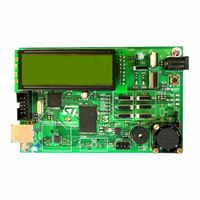
STEVAL-IFS003V1
Description
BOARD STLM75/STDS75/ST72F651
Manufacturer
STMicroelectronics
Datasheets
1.STLM75DS2F.pdf
(40 pages)
2.STDS75M2F.pdf
(39 pages)
3.STEVAL-IFS003V1.pdf
(161 pages)
4.STEVAL-IFS003V1.pdf
(4 pages)
Specifications of STEVAL-IFS003V1
Design Resources
STEVAL-IFS003V1 Gerber Files STEVAL-IFS003V1 Schematic STEVAL-IFS003V1 Bill of Materials
Sensor Type
Temperature
Sensing Range
-55°C ~ 125°C
Interface
I²C
Voltage - Supply
7.5 V ~ 19 V
Embedded
Yes, MCU, 8-Bit
Utilized Ic / Part
ST72F651, STDS75, STLM75
Silicon Manufacturer
ST Micro
Silicon Core Number
STLM75/STDS75 And ST72F651AR6
Kit Application Type
Sensing - Temperature
Application Sub Type
Temperature Sensor
Kit Contents
Board
Lead Free Status / RoHS Status
Lead free / RoHS Compliant
Sensitivity
-
Lead Free Status / Rohs Status
Lead free / RoHS Compliant
Other names
497-6238


ST72651AR6
USB INTERFACE (Cont’d)
Bit 4 = ERR Error.
This bit is set by hardware whenever one of the er-
rors listed below has occurred:
0: No error detected
1: Timeout, CRC, bit stuffing, nonstandard
Note: Refer to the ERR[2:0] bits in the USBSR
register to determine the error type.
Bit 3 = SUSP Suspend mode request.
This bit is set by hardware when a constant idle
state is present on the bus line for more than 3 ms,
indicating a suspend mode request from the USB.
The suspend request check is active immediately
after each USB reset event and is disabled by
hardware when suspend mode is forced (FSUSP
bit in the CTLR register) until the end of resume
sequence.
Bit 2 = ESUSP End Suspend mode.
This bit is set by hardware when, during suspend
mode, activity is detected that wakes the USB in-
terface up from suspend mode.
This interrupt is serviced by a specific vector, in or-
der to wake up the ST7 from HALT mode.
0: No End Suspend detected
1: End Suspend detected
Bit 1 = RESET USB reset.
This bit is set by hardware when the USB reset se-
quence is detected on the bus.
0: No USB reset signal detected
1: USB reset signal detected
Note: The DADDR, EP0R, EP1RXR, EP1TXR
and EP2RXR, EP2TXR registers are reset by a
USB reset.
Bit 0 = SOF Start of frame.
This bit is set by hardware when a SOF token is re-
ceived on the USB.
0: No SOF received
1: SOF received
Note: To avoid spurious clearing of some bits, it is
recommended to clear them using a load instruc-
tion where all bits which must not be altered are
set, and all bits to be cleared are reset. Avoid read-
modify-write instructions like AND, XOR.
68/161
1
framing or buffer overrun error detected
Doc ID 7215 Rev 4
INTERRUPT MASK REGISTER (IMR)
Read/Write
Reset Value: 0000 0000 (00h)
These bits are mask bits for all the interrupt condi-
tion bits included in the ISTR register. Whenever
one of the IMR bits is set, if the corresponding
ISTR bit is set, and the I- bit in the CC register is
cleared, an interrupt request is generated. For an
explanation of each bit, please refer to the descrip-
tion of the ISTR register.
CONTROL REGISTER (CTLR)
Read/Write
Reset value: 0000 0110 (06h)
Bit 7 = RSM Resume Detected
This bit shows when a resume sequence has start-
ed on the USB port, requesting the USB interface
to wake-up from suspend state. It can be used to
determine the cause of an ESUSP event.
0: No resume sequence detected on USB
1: Resume sequence detected on USB
Bit 6 = USB_RST USB Reset detected.
This bit shows that a reset sequence has started
on the USB. It can be used to determine the cause
of an ESUSP event (Reset sequence).
0: No reset sequence detected on USB
1: Reset sequence detected on USB
Bits 5:4 Reserved, forced by hardware to 0.
Bit 3 = RESUME Resume.
This bit is set by software to wake-up the Host
when the ST7 is in suspend mode.
0: Resume signal not forced
1: Resume signal forced on the USB bus.
Software should clear this bit after the appropriate
delay.
CTRM
RSM
7
7
USB_
RST
0
SOVR
0
M
ERRM
0
RESU
ME
SUSP
M
PDWN FSUSP FRES
ESUSP
M
RESET
M
SOFM
0
0
Related parts for STEVAL-IFS003V1
Image
Part Number
Description
Manufacturer
Datasheet
Request
R

Part Number:
Description:
BOARD EVAL SPZB260 MOD FOR STR9
Manufacturer:
STMicroelectronics
Datasheet:

Part Number:
Description:
BOARD EVAL EXTENSION SN250
Manufacturer:
STMicroelectronics
Datasheet:

Part Number:
Description:
BOARD EVAL AB-54003L-512
Manufacturer:
STMicroelectronics
Datasheet:

Part Number:
Description:
BOARD REF DESIGN RF DMOS PWR AMP
Manufacturer:
STMicroelectronics
Datasheet:

Part Number:
Description:
BOARD EVAL PWR AMP AB-84008L-470
Manufacturer:
STMicroelectronics
Datasheet:

Part Number:
Description:
BOARD EVAL FOR STM32F103XX
Manufacturer:
STMicroelectronics
Datasheet:

Part Number:
Description:
BOARD EVAL AB-54003L-512
Manufacturer:
STMicroelectronics
Datasheet:

Part Number:
Description:
BOARD SMART PLUG STM32 SPZB260PR
Manufacturer:
STMicroelectronics
Datasheet:

Part Number:
Description:
BOARD DEMO BLUETOOTH SPBT2532C2
Manufacturer:
STMicroelectronics
Datasheet:
Part Number:
Description:
ZIGBEE USB DONGLE EVAL KIT
Manufacturer:
STMicroelectronics
Datasheet:
Part Number:
Description:
STMicroelectronics [RIPPLE-CARRY BINARY COUNTER/DIVIDERS]
Manufacturer:
STMicroelectronics
Datasheet:
Part Number:
Description:
STMicroelectronics [LIQUID-CRYSTAL DISPLAY DRIVERS]
Manufacturer:
STMicroelectronics
Datasheet:

Part Number:
Description:
BOARD EVAL FOR MEMS SENSORS
Manufacturer:
STMicroelectronics
Datasheet: