STEVAL-IFS003V1 STMicroelectronics, STEVAL-IFS003V1 Datasheet - Page 64
STEVAL-IFS003V1
Manufacturer Part Number
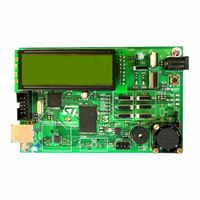
STEVAL-IFS003V1
Description
BOARD STLM75/STDS75/ST72F651
Manufacturer
STMicroelectronics
Datasheets
1.STLM75DS2F.pdf
(40 pages)
2.STDS75M2F.pdf
(39 pages)
3.STEVAL-IFS003V1.pdf
(161 pages)
4.STEVAL-IFS003V1.pdf
(4 pages)
Specifications of STEVAL-IFS003V1
Design Resources
STEVAL-IFS003V1 Gerber Files STEVAL-IFS003V1 Schematic STEVAL-IFS003V1 Bill of Materials
Sensor Type
Temperature
Sensing Range
-55°C ~ 125°C
Interface
I²C
Voltage - Supply
7.5 V ~ 19 V
Embedded
Yes, MCU, 8-Bit
Utilized Ic / Part
ST72F651, STDS75, STLM75
Silicon Manufacturer
ST Micro
Silicon Core Number
STLM75/STDS75 And ST72F651AR6
Kit Application Type
Sensing - Temperature
Application Sub Type
Temperature Sensor
Kit Contents
Board
Lead Free Status / RoHS Status
Lead free / RoHS Compliant
Sensitivity
-
Lead Free Status / Rohs Status
Lead free / RoHS Compliant
Other names
497-6238


ST72651AR6
USB INTERFACE (Cont’d)
11.3.4 USB Data Buffer Manager
The USB Data Buffer Manager performs the data
transfer between the USB interface and the two
512 Bytes RAM areas used for Endpoint 2 in both
Upload and Download modes. It also controls the
status of Endpoint 2, by setting the endpoint as
NAK when the current buffer is not yet available for
either transmission (Upload) or reception (Down-
load).
It is based on a stand-alone hardware state-ma-
chine that runs in parallel to the ST7 processing
flow. However, at any time, the ST7 software can
initialize the USB Data Buffer Manager state-ma-
chine in order to synchronize operations by writing
a ‘1’ to the CLR bit in the BUFCSR register.
Dedicated buffer status flags are defined to syn-
chronize the USB Data Buffer Manager with the
Data Transfer Coprocessor (DTC). These flags
are used by the software plug-ins provided by ST-
Microelectronics) running on the DTC.
11.3.4.1 Data Transfer Modes
In USB normal mode (MOD[1:0]=00b), the maxi-
mum memory size of Endpoint 2 is 64 bytes, and
therefore reception of 512 bytes packets requires
ST7 software intervention every 64 bytes. This
means that after a CTR interrupt the hardware
puts the Endpoint 2 status bits for the current di-
rection (transmit or receive) in NAK status. The
64/161
1
Doc ID 7215 Rev 4
ST7 software must then write the status bits to
VALID when it is ready to transmit or receive new
data.
On the contrary, in Upload or Download mode, the
physical address of Endpoint 2 is automatically in-
cremented every 64 bytes until a 512-byte buffer is
full.
Toggling between the two buffers is automatically
managed as soon as 512 bytes have been trans-
mitted to USB (Upload mode) or received from
USB (Download), if the next buffer is available:
Otherwise, the endpoint is set to invalid until a
buffer has been released by the DTC.
11.3.4.2 Switching back to Normal Mode
The USB interface is reset by hardware in Normal
mode on reception of a packet with a length below
the maximum packet size. In this case, the few
bytes are received into one of the two 512-byte
buffers and the ST7 must process by software the
data received. For this purpose, the information in-
dicating which 512-byte buffer was last addressed
is given to the ST7 by the USB Data Buffer Manag-
er (BUFNUM bit in the BUFCSR register), and the
number of received bytes is obtained by reading
the USB interface registers. With these two items
of information, the ST7 can determine what kind of
data has been received, and what action has to be
taken.
Related parts for STEVAL-IFS003V1
Image
Part Number
Description
Manufacturer
Datasheet
Request
R

Part Number:
Description:
BOARD EVAL SPZB260 MOD FOR STR9
Manufacturer:
STMicroelectronics
Datasheet:

Part Number:
Description:
BOARD EVAL EXTENSION SN250
Manufacturer:
STMicroelectronics
Datasheet:

Part Number:
Description:
BOARD EVAL AB-54003L-512
Manufacturer:
STMicroelectronics
Datasheet:

Part Number:
Description:
BOARD REF DESIGN RF DMOS PWR AMP
Manufacturer:
STMicroelectronics
Datasheet:

Part Number:
Description:
BOARD EVAL PWR AMP AB-84008L-470
Manufacturer:
STMicroelectronics
Datasheet:

Part Number:
Description:
BOARD EVAL FOR STM32F103XX
Manufacturer:
STMicroelectronics
Datasheet:

Part Number:
Description:
BOARD EVAL AB-54003L-512
Manufacturer:
STMicroelectronics
Datasheet:

Part Number:
Description:
BOARD SMART PLUG STM32 SPZB260PR
Manufacturer:
STMicroelectronics
Datasheet:

Part Number:
Description:
BOARD DEMO BLUETOOTH SPBT2532C2
Manufacturer:
STMicroelectronics
Datasheet:
Part Number:
Description:
ZIGBEE USB DONGLE EVAL KIT
Manufacturer:
STMicroelectronics
Datasheet:
Part Number:
Description:
STMicroelectronics [RIPPLE-CARRY BINARY COUNTER/DIVIDERS]
Manufacturer:
STMicroelectronics
Datasheet:
Part Number:
Description:
STMicroelectronics [LIQUID-CRYSTAL DISPLAY DRIVERS]
Manufacturer:
STMicroelectronics
Datasheet:

Part Number:
Description:
BOARD EVAL FOR MEMS SENSORS
Manufacturer:
STMicroelectronics
Datasheet: