C8051F040DK Silicon Laboratories Inc, C8051F040DK Datasheet - Page 229
C8051F040DK
Manufacturer Part Number
C8051F040DK
Description
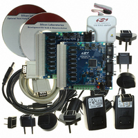
DEV KIT FOR F040/F041/F042/F043
Manufacturer
Silicon Laboratories Inc
Type
MCUr
Specifications of C8051F040DK
Contents
Evaluation Board, Power Supply, USB Cables, Adapter and Documentation
Processor To Be Evaluated
C8051F04x
Interface Type
USB
Silicon Manufacturer
Silicon Labs
Core Architecture
8051
Silicon Core Number
C8051F040
Silicon Family Name
C8051F04x
Lead Free Status / RoHS Status
Contains lead / RoHS non-compliant
For Use With/related Products
Silicon Laboratories C8051 F040, 041, 042, 043 MCUs
Lead Free Status / Rohs Status
Lead free / RoHS Compliant
Other names
336-1205
Available stocks
Company
Part Number
Manufacturer
Quantity
Price
Company:

Part Number:
C8051F040DK
Manufacturer:
SiliconL
Quantity:
9


18.1.1. CAN Controller Timing
The CAN controller’s system clock (f
external oscillator (such as a quartz crystal) is typically required due to the high accuracy requirements for
CAN communication. Refer to Section “4.10.4 Oscillator Tolerance Range” in the Bosch CAN User’s Guide
for further information regarding this topic.
18.1.2. Example Timing Calculation for 1 Mbit/Sec Communication
This example shows how to configure the CAN contoller timing parameters for a 1 Mbit/Sec bit rate.
Table 18.1 shows timing-related system parameters needed for the calculation.
Each bit transmitted on a CAN network has 4 segments (Sync_Seg, Prop_Seg, Phase_Seg1, and
Phase_Seg2), as shown in Figure 18.3. The sum of these segments determines the CAN bit time (1/bit
rate). In this example, the desired bit rate is 1 Mbit/sec; therefore, the desired bit time is 1000 ns.
Notes:
CIP-51 system clock (SYSCLK)
CAN Controller system clock
1. The CAN time quantum (t
2. The Baud Rate Prescaler (BRP) is defined as the value of the BRP Extension Register plus 1. The BRP
3. Based on an ISO-11898 compliant transceiver. CAN does not specify a physical layer.
Propagation delay time
CAN clock period (t
CAN time quantum (t
are often specified in integer multiples of the time quantum.
Extension Register has a reset value of 0x0000; the Baud Rate Prescaler has a reset value of 1.
CAN bus length
Parameter
(f
sys
1t
)
q
Figure 18.3. Four Segments of a CAN Bit Time
Sync_Seg
Table 18.1. Background System Information
sys
q
1t
)
)
3
Prop_Seg
1 to 8 t
q
q
) is the smallest unit of time recognized by the CAN contoller. Bit timing parameters
sys
q
CAN Bit Time (4 to 25 t
22.1184 MHz
22.1184 MHz
) is derived from the CIP-51 system clock (SYSCLK). Note that an
45.211 ns
45.211 ns
400 ns
Value
10 m
Rev. 1.5
Phase_Seg1
1 to 8 t
22.1184 MHz quartz crystal is connected between
C8051F040/1/2/3/4/5/6/7
External oscillator in ‘Crystal Oscillator Mode’. A
2 x (transceiver loop delay + bus line delay)
5 ns/m signal delay between CAN nodes.
q
q
)
Derived from t
Derived from SYSCLK.
Phase_Seg2
Derived from 1/f
XTAL1 and XTAL2.
Sample Point
Description
1 to 8 t
sys
q
x BRP
sys
.
1,2
229
Related parts for C8051F040DK
Image
Part Number
Description
Manufacturer
Datasheet
Request
R

Part Number:
Description:
SMD/C°/SINGLE-ENDED OUTPUT SILICON OSCILLATOR
Manufacturer:
Silicon Laboratories Inc
Part Number:
Description:
Manufacturer:
Silicon Laboratories Inc
Datasheet:
Part Number:
Description:
N/A N/A/SI4010 AES KEYFOB DEMO WITH LCD RX
Manufacturer:
Silicon Laboratories Inc
Datasheet:
Part Number:
Description:
N/A N/A/SI4010 SIMPLIFIED KEY FOB DEMO WITH LED RX
Manufacturer:
Silicon Laboratories Inc
Datasheet:
Part Number:
Description:
N/A/-40 TO 85 OC/EZLINK MODULE; F930/4432 HIGH BAND (REV E/B1)
Manufacturer:
Silicon Laboratories Inc
Part Number:
Description:
EZLink Module; F930/4432 Low Band (rev e/B1)
Manufacturer:
Silicon Laboratories Inc
Part Number:
Description:
I°/4460 10 DBM RADIO TEST CARD 434 MHZ
Manufacturer:
Silicon Laboratories Inc
Part Number:
Description:
I°/4461 14 DBM RADIO TEST CARD 868 MHZ
Manufacturer:
Silicon Laboratories Inc
Part Number:
Description:
I°/4463 20 DBM RFSWITCH RADIO TEST CARD 460 MHZ
Manufacturer:
Silicon Laboratories Inc
Part Number:
Description:
I°/4463 20 DBM RADIO TEST CARD 868 MHZ
Manufacturer:
Silicon Laboratories Inc
Part Number:
Description:
I°/4463 27 DBM RADIO TEST CARD 868 MHZ
Manufacturer:
Silicon Laboratories Inc
Part Number:
Description:
I°/4463 SKYWORKS 30 DBM RADIO TEST CARD 915 MHZ
Manufacturer:
Silicon Laboratories Inc
Part Number:
Description:
N/A N/A/-40 TO 85 OC/4463 RFMD 30 DBM RADIO TEST CARD 915 MHZ
Manufacturer:
Silicon Laboratories Inc
Part Number:
Description:
I°/4463 20 DBM RADIO TEST CARD 169 MHZ
Manufacturer:
Silicon Laboratories Inc