MAX3420EEVKIT-2+ Maxim Integrated Products, MAX3420EEVKIT-2+ Datasheet - Page 5
MAX3420EEVKIT-2+
Manufacturer Part Number
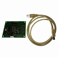
MAX3420EEVKIT-2+
Description
EVAL KIT FOR MAX3420E
Manufacturer
Maxim Integrated Products
Specifications of MAX3420EEVKIT-2+
Main Purpose
Interface, USB 2.0 Slave
Embedded
No
Utilized Ic / Part
MAX3420E
Primary Attributes
Full Speed (12Mbps), SPI Interface, No Custom USB Drivers
Secondary Attributes
4 GPI Pushbuttons, 4 GPO LEDs
Lead Free Status / RoHS Status
Lead free / RoHS Compliant


The SPI master controls the MAX3420E by reading and
writing 21 registers (Table 1). For a complete descrip-
tion of register contents, please refer to the “MAX3420E
Programming Guide.” A register access consists of the
SPI master first writing an SPI command byte, followed
by reading or writing the contents of the addressed
register. All SPI transfers are MSB first. The command
byte contains the register address, a direction bit (read
= 0, write = 1), and the ACKSTAT bit (Figure 4). The SPI
master addresses the MAX3420E registers by writing
the binary value of the register number in the Reg4
through Reg0 bits of the command byte. For example,
to access the IOPINS (R20) register, the Reg4 through
Figure 4. SPI Command Byte
Figure 5. USB Status Bits Clocked Out as First Byte of Every Transfer (Full-Duplex Mode Only)
TQFN-EP
SUSPIRQ
17
18
19
20
21
22
23
24
—
—
Reg4
b7
b7
PIN
9, 16, 25,
22, 23
LQFP
28
24
26
27
29
30
31
32
—
URESIRQ
_______________________________________________________________________________________
Reg3
b6
b6
VBCOMP
NAME
GPIN0
GPIN1
GPIN2
GPIN3
N.C.
V
XO
EP
XI
CC
Register Description
SUDAVIRQ
Reg2
OUTPUT
b5
INPUT/
b5
Output
Input
Input
Input
Input
Input
—
USB Transceiver Power-Supply Input. Connect V
supply. Bypass V
V
V
comparator to allow the SPI master to detect (through an interrupt or checking a
register bit) the presence or loss of power on V
with a 1.0μF ceramic capacitor.
Crystal Oscillator Input. Connect XI to one side of a parallel resonant 12MHz
±0.25% crystal and a capacitor to GND. XI can also be driven by an external
clock referenced to V
Crystal Oscillator Output. Connect XO to the other side of a parallel resonant
12MHz ±0.25% crystal and a capacitor to GND. Leave XO unconnected if XI is
driven with an external source.
General-Purpose Inputs. GPIN3–GPIN0 are connected to V
resistors. GPIN3–GPIN0 logic levels are referenced to the voltage on V
SPI master samples GPIN3–GPIN0 states by reading bit 7 through bit 4 of the
IOPINS (R20) register. Writing to these bits has no effect.
No Internal Connection
Exposed Paddle (TQFN only). Connect EP to GND.
CC
BUS
IN3BAVIRQ
pin as possible.
Reg1
Comparator Input. VBCOMP is internally connected to a voltage
b4
b4
USB Peripheral Controller
CC
IN2BAVIRQ
Reg0 bits would be as follows: Reg4 = 1, Reg3 = 0,
Reg2 = 1, Reg1 = 0, Reg0 = 0. The DIR (direction) bit
determines the direction for the data transfer. DIR = 1
means the data byte(s) will be written to the register,
and DIR = 0 means the data byte(s) will be read from
the register. The ACKSTAT bit sets the ACKSTAT bit in
the EPSTALLS (R9) register. The SPI master sets this
bit to indicate that it has finished servicing a CONTROL
transfer. Since the bit is frequently used, having it in the
SPI command byte improves firmware efficiency. In SPI
full-duplex mode, the MAX3420E clocks out eight USB
status bits as the command byte is clocked in (Figure
5). In half-duplex mode, these status bits are accessed
in the normal way, as register bits.
Reg0
to ground with a 1.0μF ceramic capacitor as close to the
CC
b3
b3
.
with SPI Interface
Pin Description (continued)
OUT1DAVIRQ
FUNCTION
b2
b2
0
BUS
CC
OUT0DAVIRQ
. Bypass VBCOMP to ground
to a positive 3.3V power
DIR
b1
b1
L
with internal pullup
IN0BAVIRQ
ACKSTAT
L
b0
b0
. The
5
Related parts for MAX3420EEVKIT-2+
Image
Part Number
Description
Manufacturer
Datasheet
Request
R

Part Number:
Description:
MAX7528KCWPMaxim Integrated Products [CMOS Dual 8-Bit Buffered Multiplying DACs]
Manufacturer:
Maxim Integrated Products
Datasheet:
Part Number:
Description:
Single +5V, fully integrated, 1.25Gbps laser diode driver.
Manufacturer:
Maxim Integrated Products
Datasheet:
Part Number:
Description:
Single +5V, fully integrated, 155Mbps laser diode driver.
Manufacturer:
Maxim Integrated Products
Datasheet:
Part Number:
Description:
VRD11/VRD10, K8 Rev F 2/3/4-Phase PWM Controllers with Integrated Dual MOSFET Drivers
Manufacturer:
Maxim Integrated Products
Datasheet:
Part Number:
Description:
Highly Integrated Level 2 SMBus Battery Chargers
Manufacturer:
Maxim Integrated Products
Datasheet:
Part Number:
Description:
Current Monitor and Accumulator with Integrated Sense Resistor; ; Temperature Range: -40°C to +85°C
Manufacturer:
Maxim Integrated Products
Part Number:
Description:
TSSOP 14/A�/RS-485 Transceivers with Integrated 100O/120O Termination Resis
Manufacturer:
Maxim Integrated Products
Part Number:
Description:
TSSOP 14/A�/RS-485 Transceivers with Integrated 100O/120O Termination Resis
Manufacturer:
Maxim Integrated Products
Part Number:
Description:
QFN 16/A�/AC-DC and DC-DC Peak-Current-Mode Converters with Integrated Step
Manufacturer:
Maxim Integrated Products
Part Number:
Description:
TDFN/A/65V, 1A, 600KHZ, SYNCHRONOUS STEP-DOWN REGULATOR WITH INTEGRATED SWI
Manufacturer:
Maxim Integrated Products
Part Number:
Description:
Integrated Temperature Controller f
Manufacturer:
Maxim Integrated Products
Part Number:
Description:
SOT23-6/I�/45MHz to 650MHz, Integrated IF VCOs with Differential Output
Manufacturer:
Maxim Integrated Products
Part Number:
Description:
SOT23-6/I�/45MHz to 650MHz, Integrated IF VCOs with Differential Output
Manufacturer:
Maxim Integrated Products
Part Number:
Description:
EVALUATION KIT/2.4GHZ TO 2.5GHZ 802.11G/B RF TRANSCEIVER WITH INTEGRATED PA
Manufacturer:
Maxim Integrated Products
Part Number:
Description:
QFN/E/DUAL PCIE/SATA HIGH SPEED SWITCH WITH INTEGRATED BIAS RESISTOR
Manufacturer:
Maxim Integrated Products
Datasheet: