MAX3420EEVKIT-2+ Maxim Integrated Products, MAX3420EEVKIT-2+ Datasheet - Page 20
MAX3420EEVKIT-2+
Manufacturer Part Number
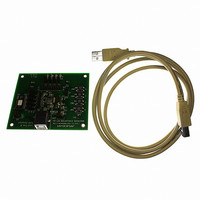
MAX3420EEVKIT-2+
Description
EVAL KIT FOR MAX3420E
Manufacturer
Maxim Integrated Products
Specifications of MAX3420EEVKIT-2+
Main Purpose
Interface, USB 2.0 Slave
Embedded
No
Utilized Ic / Part
MAX3420E
Primary Attributes
Full Speed (12Mbps), SPI Interface, No Custom USB Drivers
Secondary Attributes
4 GPI Pushbuttons, 4 GPO LEDs
Lead Free Status / RoHS Status
Lead free / RoHS Compliant


The V
MAX3420E feature. Because the µP is powered
whether the USB device is plugged in or not, it needs
some way to detect a plug-in event. A comparator
inside the MAX3420E checks for a valid V
tion on VBCOMP and provides a connect status bit to
the µP. Once connected, the µP can delay the logical
connection to the USB bus to perform any required ini-
tialization, and then connect by setting the CONNECT
bit to 1 in the MAX3420E register USBCTL (R15). This
connects the internal 1.5kΩ resistor from D+ to V
signal the host that a device has been plugged in.
If a host turns off V
the USB rev. 2.0 specification requires that the device
must not power its 1.5kΩ pullup resistor connected to
D+. The MAX3420E has two features to help service
this event. First, the NOVBUSIRQ bit indicates the loss
of V
(V
pullup resistor anytime V
the CONNECT bit setting.
USB Peripheral Controller
with SPI Interface
Figure 17. MAX3420E in a Self-Powered Application
20
BUS
BUS
______________________________________________________________________________________
BUS
gate) to instruct the MAX3420E to disconnect the
. Second, the µP can set a bit called VBGATE
"B" CONNECTOR
detect input, VBCOMP, is an important
USB
BUS
V
GND
BUS
while the device is connected,
BUS
D+
D-
goes away, regardless of
CERAMIC
33Ω
33Ω
1.0μF
BUS
CERAMIC
1.0μF
connec-
RES
D+
D-
VBCOMP
CC
V
CC
, to
V
GND
L
0.1μF
The MAX3420E requires a crystal with the following
specifications:
Frequency: 12MHz ±0.25%
C
C
Drive level: 200µW
Series resonance resistance: 60Ω max
Note: Series resonance resistance is the resistance
observed when the resonator is in the series resonant
condition. This is a parameter often stated by quartz crys-
tal vendors and is called R1. When a resonator is used in
the parallel resonant mode with an external load capaci-
tance, as is the case with the MAX3420E oscillator circuit,
the effective resistance is sometimes stated. This effec-
tive resistance at the loaded frequency of oscillation is:
For typical C
tance can be greater than R1 by a factor of 2.
MAX3420E
LOAD
O
: 7pF max
: 18pF
GPIN
4
C
XI
GPIO
O
R1 x ( 1 + (C
GPOUT
XI
and C
12MHz
4
XO
MOSI
MISO
SCLK
LOAD
GPX
C
INT
SS
XO
O
values, the effective resis-
/ C
N.C.
N.C.
LOAD
Crystal Selection
))
+3.3V
μP
2
Related parts for MAX3420EEVKIT-2+
Image
Part Number
Description
Manufacturer
Datasheet
Request
R

Part Number:
Description:
MAX7528KCWPMaxim Integrated Products [CMOS Dual 8-Bit Buffered Multiplying DACs]
Manufacturer:
Maxim Integrated Products
Datasheet:
Part Number:
Description:
Single +5V, fully integrated, 1.25Gbps laser diode driver.
Manufacturer:
Maxim Integrated Products
Datasheet:
Part Number:
Description:
Single +5V, fully integrated, 155Mbps laser diode driver.
Manufacturer:
Maxim Integrated Products
Datasheet:
Part Number:
Description:
VRD11/VRD10, K8 Rev F 2/3/4-Phase PWM Controllers with Integrated Dual MOSFET Drivers
Manufacturer:
Maxim Integrated Products
Datasheet:
Part Number:
Description:
Highly Integrated Level 2 SMBus Battery Chargers
Manufacturer:
Maxim Integrated Products
Datasheet:
Part Number:
Description:
Current Monitor and Accumulator with Integrated Sense Resistor; ; Temperature Range: -40°C to +85°C
Manufacturer:
Maxim Integrated Products
Part Number:
Description:
TSSOP 14/A�/RS-485 Transceivers with Integrated 100O/120O Termination Resis
Manufacturer:
Maxim Integrated Products
Part Number:
Description:
TSSOP 14/A�/RS-485 Transceivers with Integrated 100O/120O Termination Resis
Manufacturer:
Maxim Integrated Products
Part Number:
Description:
QFN 16/A�/AC-DC and DC-DC Peak-Current-Mode Converters with Integrated Step
Manufacturer:
Maxim Integrated Products
Part Number:
Description:
TDFN/A/65V, 1A, 600KHZ, SYNCHRONOUS STEP-DOWN REGULATOR WITH INTEGRATED SWI
Manufacturer:
Maxim Integrated Products
Part Number:
Description:
Integrated Temperature Controller f
Manufacturer:
Maxim Integrated Products
Part Number:
Description:
SOT23-6/I�/45MHz to 650MHz, Integrated IF VCOs with Differential Output
Manufacturer:
Maxim Integrated Products
Part Number:
Description:
SOT23-6/I�/45MHz to 650MHz, Integrated IF VCOs with Differential Output
Manufacturer:
Maxim Integrated Products
Part Number:
Description:
EVALUATION KIT/2.4GHZ TO 2.5GHZ 802.11G/B RF TRANSCEIVER WITH INTEGRATED PA
Manufacturer:
Maxim Integrated Products
Part Number:
Description:
QFN/E/DUAL PCIE/SATA HIGH SPEED SWITCH WITH INTEGRATED BIAS RESISTOR
Manufacturer:
Maxim Integrated Products
Datasheet: