MAX3420EEVKIT-2+ Maxim Integrated Products, MAX3420EEVKIT-2+ Datasheet
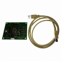
EVAL KIT FOR MAX3420E

MAX3420EEVKIT-2+

Manufacturer Part Number
MAX3420EEVKIT-2+
Description
EVAL KIT FOR MAX3420E
Manufacturer
Maxim Integrated Products
Datasheets

Specifications of MAX3420EEVKIT-2+

Main Purpose
Interface, USB 2.0 Slave
Embedded
No
Utilized Ic / Part
MAX3420E
Primary Attributes
Full Speed (12Mbps), SPI Interface, No Custom USB Drivers
Secondary Attributes
4 GPI Pushbuttons, 4 GPO LEDs
Lead Free Status / RoHS Status
Lead free / RoHS Compliant
The MAX3420E evaluation kit-2 (EV kit-2) provides a
proven design to evaluate the MAX3420E USB peri-
pheral controller with SPI™ interface. The EV kit-2
board is jumper-connected to an Atmel
microcontroller by default, but can also be connected
to any SPI master. The MAX3420E EV kit-2 adds USB
functionality to any microcontroller, microprocessor,
DSP, CPLD, FPGA, or ASIC with an SPI master inter-
face or five GPIO lines can connect to the MAX3420E
EV kit-2.
The EV kit-2 board comes with the MAX3420EECJ+
installed.
SPI is a trademark of Motorola, Inc.
Atmel is a registered trademark of Atmel Corp.
19-0696; Rev 0; 12/06
Note: Indicate that you are using the MAX3420E when contacting
these component suppliers.
For pricing, delivery, and ordering information, please contact Maxim/Dallas Direct! at
1-888-629-4642, or visit Maxim’s website at www.maxim-ic.com.
Murata
TDK
DESIGNATION
C2, C3, C6, C8
SUPPLIER
C1, C7
C4, C5
D1–D4
D5
H1
H2
H3
770-436-1300
847-803-6100
________________________________________________________________ Maxim Integrated Products
QTY
PHONE
2
4
2
4
1
1
1
1
Component Suppliers
General Description
2.2µF ±20%, 6.3V X5R ceramic
capacitors (0603)
TDK C1608X5R0J225K or
C1608X5R0J225M
1µF ±20%, 6.3V X5R ceramic
capacitors (0603)
TDK C1608X5R0J105K or
C1608X5R0J105M
18pF ±5%, 50V C0G ceramic
capacitors (0402)
Murata GRM1555C1H180J
TDK C1005C0G1H180J
Green LEDs (0603)
Stanley Electric BG1111C-TR
Panasonic LNJ314G8TRA or
LNJ308G84RA
Red LED (0603)
Panasonic LNJ208R8ARA
Dual-row, 20-pin (2 x 10) header
Single-row, 8-pin header
Dual-row, 6-pin (2 x 3) header
www.murata.com
www.component.tdk.com
DESCRIPTION
WEBSITE
®
ATtiny2313
MAX3420E Evaluation Kit-2
o Complies with USB 2.0 (Full Speed)
o Custom USB Drivers Not Required
o USB Powered
o USB Power LED Indicator
o USB Cable Included
o On-Board ATtiny2313 Microcontroller
o Four GPI Port-Connected Pushbuttons
o Four GPO Port LED Indicators
o 20-Pin Signal Header to Connect the MAX3420E
o Proven PCB Layout
o Fully Assembled and Tested
+ Denotes a lead-free and RoHS-compliant EV kit.
MAX3420EEVKIT-2+
DESIGNATION
to Any Microcontroller
TP1, TP2, TP3
PART NUMBER
JU10, JU11
R3, R6–R9
SW1–SW4
JU1–JU5,
JU6–JU9
R1, R2
R4, R5
U1
P1
QTY
7
4
1
2
5
2
4
3
1
Ordering Information
TYPE
3-pin headers
2-pin headers
USB type B right-angle receptacle
Assmann AU-Y1007-R
33.2Ω ±1% resistors (0603)
(use lead-free parts only)
150Ω ±5% resistors (0603)
(use lead-free parts only)
10kΩ ±5% resistors (0603)
(use lead-free parts only)
Pushbutton switches
Panasonic EQV-PHP03T
Mini test points (black)
Keystone Electronics 5001
MAX3420EECJ+ USB
peripheral controller
(32-pin, 7mm x 7mm x 1.4mm,
TQFP)
EV kit
Component List
DESCRIPTION
PC INTERFACE
Features
USB
1

Related parts for MAX3420EEVKIT-2+

MAX3420EEVKIT-2+ Summary of contents

Page 1

... Four GPI Port-Connected Pushbuttons o Four GPO Port LED Indicators o 20-Pin Signal Header to Connect the MAX3420E to Any Microcontroller o Proven PCB Layout o Fully Assembled and Tested WEBSITE PART NUMBER MAX3420EEVKIT-2+ + Denotes a lead-free and RoHS-compliant EV kit. DESIGNATION JU1–JU5, JU10, JU11 JU6–JU9 P1 R1, R2 R3, R6– ...

Page 2

... WordPad editor. 10) Stop the HID keyboard emulator by pressing the port 3 pushbutton switch (SW4) again. The port 3 pushbutton starts and stops the emulator. Component List (continued) QTY DESCRIPTION 12MHz crystal; 18pF load 1 (HCM49 SMD case) Citizen HCM49-12.000MABJ-UT 11 Shunts 4 Rubber bumps 1 MAX3420EEVKIT-2+ PCB ...

Page 3

Figure 2. Found New Hardware | USB Human Interface Device Window Detailed Description of Hardware Tables 1 and 2 describe the function of each pushbutton and LED during the HID keyboard emulator demo. Tables 3 through 6 explain the functionality ...

Page 4

MAX3420E Evaluation Kit-2 Table 3. SPI Bus Selection (JU1–JU5) JUMPER SHUNT POSITION 1-2* JU1 2-3 1-2* JU2 2-3 1-2* JU3 2-3 1-2* JU4 2-3 1-2* JU5 2-3 *Default position. Table 4. GPO 0–3 LED Connection (JU6–JU9) JUMPER SHUNT POSITION 1-2* ...

Page 5

Table 7. Header H1 Pin Description PIN NAME 1 GPX 2 CONINT 3 CONMISO 4 CONMOSI 5 CONSCLK 6 CONSS 7 GPO3 RES GPO2 11 GND 12 GND 13 GPO0 14 GPO1 15 GPI2 16 ...

Page 6

MAX3420E Evaluation Kit-2 Table 8. Header H2 Pin Description (SPI Test Points) PIN NAME 1 — 2 GPX 3 MOSI 4 MISO SCLK 7 INT 8 GND Table 9. Header H3 Pin Description (ISP Connector) PIN NAME ...

Page 7

Figure 3. MAX3420E EV Kit-2 Schematic _______________________________________________________________________________________ MAX3420E Evaluation Kit-2 GPO3 GPO2 GPO1 GPO0 7 ...

Page 8

MAX3420E Evaluation Kit-2 Figure 4. MAX3420E EV Kit-2 Component Placement Guide—Component Side 8 _______________________________________________________________________________________ ...

Page 9

Figure 5. MAX3420E EV Kit-2 PCB Layout—Component Side _______________________________________________________________________________________ MAX3420E Evaluation Kit-2 9 ...

Page 10

... Maxim cannot assume responsibility for use of any circuitry other than circuitry entirely embodied in a Maxim product. No circuit patent licenses are implied. Maxim reserves the right to change the circuitry and specifications without notice at any time. 10 ________________Maxim Integrated Products, 120 San Gabriel Drive, Sunnyvale, CA 94086 408-737-7600 © 2006 Maxim Integrated Products ...

Related keywords