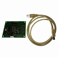
MAX3420EEVKIT-2+ Maxim Integrated Products, MAX3420EEVKIT-2+ Datasheet - Page 21

MAX3420EEVKIT-2+
Manufacturer Part Number
MAX3420EEVKIT-2+
Description
EVAL KIT FOR MAX3420E
Manufacturer
Maxim Integrated Products
Specifications of MAX3420EEVKIT-2+
Main Purpose
Interface, USB 2.0 Slave
Embedded
No
Utilized Ic / Part
MAX3420E
Primary Attributes
Full Speed (12Mbps), SPI Interface, No Custom USB Drivers
Secondary Attributes
4 GPI Pushbuttons, 4 GPO LEDs
Lead Free Status / RoHS Status
Lead free / RoHS Compliant
D+, D-, and VBCOMP possess extra protection against
static electricity to protect the devices up to ±15kV. The
ESD structures withstand high ESD in all operating
modes: normal operation, suspend mode, and pow-
ered down. VBCOMP and V
capacitors connected to ground as close to the pins as
Figure 19. Human Body Model Current Waveform
Figure 20. IEC 61000-4-2 ESD Test Model
Figure 18. Human Body ESD Test Models
AMPERES
VOLTAGE
SOURCE
HIGH-
VOLTAGE
SOURCE
DC
HIGH-
DC
I
P
36.8%
100%
90%
10%
CHARGE-CURRENT-
CHARGE-CURRENT-
0
LIMIT RESISTOR
50MΩ to 100MΩ
LIMIT RESISTOR
0
t
R
1MΩ
RL
R
C
150pF
C
100pF
______________________________________________________________________________________
C s
C s
STORAGE
CAPACITOR
CURRENT WAVEFORM
STORAGE
CAPACITOR
RESISTANCE
TIME
DISCHARGE
RESISTANCE
DISCHARGE
1.5kΩ
330Ω
R
R
D
D
t
DL
CC
I r
ESD Protection
require 1µF ceramic
PEAK-TO-PEAK RINGING
(NOT DRAWN TO SCALE)
DEVICE
UNDER
TEST
DEVICE
UNDER
TEST
USB Peripheral Controller
possible. D+, D-, and VBCOMP provide protection to
the following limits:
ESD performance depends on a variety of conditions.
Contact Maxim for a reliability report that documents
test setup, test methodology, and test results.
Figure 18 shows the Human Body Model, and Figure 19
shows the current waveform generated when dis-
charged into a low impedance. This model consists of
a 100pF capacitor charged to the ESD voltage of inter-
est, which then discharges into the test device through
a 1.5kΩ resistor.
The IEC 61000-4-2 standard covers ESD testing and
performance of finished equipment. It does not specifi-
cally refer to integrated circuits. The major difference
between tests done using the Human Body Model and
IEC 61000-4-2 is a higher peak current in IEC 61000-4-
2, due to lower series resistance. Hence, the ESD with-
stand voltage measured to IEC 61000-4-2 generally is
lower than that measured using the Human Body
Model. Figure 20 shows the IEC 61000-4-2 model. The
Contact Discharge method connects the probe to the
device before the probe is charged. The Air-Gap
Discharge test involves approaching the device with a
charged probe.
The MAX3420E withstands V
on the USB connector side of the 33Ω series resistors.
PROCESS: BiCMOS
For the latest package outline information and land patterns,
go to www.maxim-ic.com/packages. Note that a “+”, “#”, or
“-” in the package code indicates RoHS status only. Package
drawings may show a different suffix character, but the drawing
pertains to the package regardless of RoHS status.
• ±15kV using the Human Body Model
• ±8kV using the Contact Discharge method specified
• ±12kV using the IEC 61000-4-2 Air Gap Method
in IEC 61000-4-2
24 TQFN-EP
PACKAGE
32 LQFP
TYPE
with SPI Interface
Short-Circuit Protection
PACKAGE
T2444+4
C32+1
CODE
Package Information
Chip Information
ESD Test Conditions
BUS
Human Body Model
OUTLINE
21-0139
21-0054
NO.
shorts to D+ and D-
IEC 61000-4-2
PATTERN NO.
90-0022
90-0111
LAND
21


