MAX3420EEVKIT-2+ Maxim Integrated Products, MAX3420EEVKIT-2+ Datasheet - Page 12
MAX3420EEVKIT-2+
Manufacturer Part Number
MAX3420EEVKIT-2+
Description
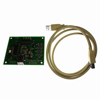
EVAL KIT FOR MAX3420E
Manufacturer
Maxim Integrated Products
Specifications of MAX3420EEVKIT-2+
Main Purpose
Interface, USB 2.0 Slave
Embedded
No
Utilized Ic / Part
MAX3420E
Primary Attributes
Full Speed (12Mbps), SPI Interface, No Custom USB Drivers
Secondary Attributes
4 GPI Pushbuttons, 4 GPO LEDs
Lead Free Status / RoHS Status
Lead free / RoHS Compliant


The MAX3420E contains the digital logic and analog
circuitry necessary to implement a full-speed USB
peripheral that complies with the USB specification rev
2.0. ESD protection of ±15kV is provided on D+, D-,
and VBCOMP. The MAX3420E features an internal USB
transceiver and an internal 1.5kΩ resistor that connects
between D+ and V
(CONNECT). This allows a USB peripheral to control
the logical connection to the USB host. Any SPI master
can communicate with the MAX3420E through the SPI
slave interface that operates in SPI mode (0,0) or (1,1).
An SPI master accesses the MAX3420E by reading and
writing to internal registers. A typical data transfer con-
sists of writing a first byte that sets a register address
and direction with additional bytes reading or writing
data to the register or internal FIFO.
The MAX3420E contains 384 bytes of endpoint buffer
memory, implementing the following endpoints:
The choice to use EP1, EP2, EP3 as BULK or INTER-
RUPT endpoints is strictly a function of the endpoint
descriptors that the SPI master returns to the USB host
during enumeration.
USB Peripheral Controller
with SPI Interface
(V
12
CC
• EP0: 64-byte bidirectional CONTROL endpoint
• EP3: 64-byte BULK/INT IN endpoint
• EP1: 2 x 64-byte double-buffered BULK/INT
• EP2: 2 x 64-byte double-buffered BULK/INT IN
OUT endpoint
endpoint
______________________________________________________________________________________
= +3.3V, V
L
= +3.3V, T
CC
under the control of a register bit
Detailed Description
A
= +25°C.)
-1
0
4
3
1
2
0
10
20
EYE DIAGRAM
30
TIME (ns)
40
The MAX3420E register set and SPI interface is optimized
to reduce SPI traffic. An interrupt output pin, INT, notifies
the SPI master when USB service is required: when a
packet arrives, a packet is sent, or the host suspends or
resumes bus activity. Double-buffered endpoints help
sustain bandwidth by allowing data to move concurrently
over USB and the SPI interface.
Power the USB transceiver by applying a positive 3.3V
supply to V
ceramic capacitor as close to the V
The MAX3420E digital core is powered though the V
pin. V
face and all other inputs and outputs. Connect V
system’s logic-level power supply. Internal level transla-
tors and V
pose inputs and outputs to operate at a system voltage
between 1.71V and 3.6V.
The MAX3420E features a USB V
VBCOMP. The VBCOMP pin can withstand input volt-
ages up to 6V. Bypass VBCOMP to GND with a 1.0µF
ceramic capacitor. According to USB specification rev
2.0, a self-powered USB device must not power the
1.5kΩ pullup resistor on D+ if the USB host turns off
V
comparator so that the SPI master can detect the loss
of V
Typical Operating Characteristics
BUS
50
BUS
. VBCOMP is internally connected to a voltage
L
also acts as a reference level for the SPI inter-
60
(through an interrupt (INT) or checking a bit
L
allow the SPI interface and all general-pur-
70
CC
. Bypass V
80
CC
to GND with a 1.0µF
CC
BUS
pin as possible.
detector input,
VBCOMP
L
to the
V
CC
V
L
L
Related parts for MAX3420EEVKIT-2+
Image
Part Number
Description
Manufacturer
Datasheet
Request
R

Part Number:
Description:
MAX7528KCWPMaxim Integrated Products [CMOS Dual 8-Bit Buffered Multiplying DACs]
Manufacturer:
Maxim Integrated Products
Datasheet:
Part Number:
Description:
Single +5V, fully integrated, 1.25Gbps laser diode driver.
Manufacturer:
Maxim Integrated Products
Datasheet:
Part Number:
Description:
Single +5V, fully integrated, 155Mbps laser diode driver.
Manufacturer:
Maxim Integrated Products
Datasheet:
Part Number:
Description:
VRD11/VRD10, K8 Rev F 2/3/4-Phase PWM Controllers with Integrated Dual MOSFET Drivers
Manufacturer:
Maxim Integrated Products
Datasheet:
Part Number:
Description:
Highly Integrated Level 2 SMBus Battery Chargers
Manufacturer:
Maxim Integrated Products
Datasheet:
Part Number:
Description:
Current Monitor and Accumulator with Integrated Sense Resistor; ; Temperature Range: -40°C to +85°C
Manufacturer:
Maxim Integrated Products
Part Number:
Description:
TSSOP 14/A�/RS-485 Transceivers with Integrated 100O/120O Termination Resis
Manufacturer:
Maxim Integrated Products
Part Number:
Description:
TSSOP 14/A�/RS-485 Transceivers with Integrated 100O/120O Termination Resis
Manufacturer:
Maxim Integrated Products
Part Number:
Description:
QFN 16/A�/AC-DC and DC-DC Peak-Current-Mode Converters with Integrated Step
Manufacturer:
Maxim Integrated Products
Part Number:
Description:
TDFN/A/65V, 1A, 600KHZ, SYNCHRONOUS STEP-DOWN REGULATOR WITH INTEGRATED SWI
Manufacturer:
Maxim Integrated Products
Part Number:
Description:
Integrated Temperature Controller f
Manufacturer:
Maxim Integrated Products
Part Number:
Description:
SOT23-6/I�/45MHz to 650MHz, Integrated IF VCOs with Differential Output
Manufacturer:
Maxim Integrated Products
Part Number:
Description:
SOT23-6/I�/45MHz to 650MHz, Integrated IF VCOs with Differential Output
Manufacturer:
Maxim Integrated Products
Part Number:
Description:
EVALUATION KIT/2.4GHZ TO 2.5GHZ 802.11G/B RF TRANSCEIVER WITH INTEGRATED PA
Manufacturer:
Maxim Integrated Products
Part Number:
Description:
QFN/E/DUAL PCIE/SATA HIGH SPEED SWITCH WITH INTEGRATED BIAS RESISTOR
Manufacturer:
Maxim Integrated Products
Datasheet: