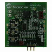
MCP1631RD-MCC2 Microchip Technology, MCP1631RD-MCC2 Datasheet - Page 251

MCP1631RD-MCC2
Manufacturer Part Number
MCP1631RD-MCC2
Description
REFERENCE DESIGN MCP1631HV
Manufacturer
Microchip Technology
Datasheets
1.MCP1631VHVT-330EST.pdf
(34 pages)
2.MCP1631HV-330EST.pdf
(54 pages)
3.MCP1631RD-MCC2.pdf
(20 pages)
4.MCP1631RD-MCC2.pdf
(328 pages)
Specifications of MCP1631RD-MCC2
Main Purpose
Power Management, Battery Charger
Embedded
Yes, MCU, 8-Bit
Utilized Ic / Part
MCP1631HV, PIC16F883
Primary Attributes
1 ~ 2 Cell- Li-Ion, 1 ~ 5 Cell- NiCd/NiMH, 1 ~ 2 1W LEDs
Secondary Attributes
Status LEDs
Silicon Manufacturer
Microchip
Application Sub Type
Battery Charger
Kit Application Type
Power Management - Battery
Silicon Core Number
MCP1631HV, PIC16F883
Kit Contents
Board
Lead Free Status / RoHS Status
Lead free / RoHS Compliant
Lead Free Status / RoHS Status
Lead free / RoHS Compliant
- MCP1631VHVT-330EST PDF datasheet
- MCP1631HV-330EST PDF datasheet #2
- MCP1631RD-MCC2 PDF datasheet #3
- MCP1631RD-MCC2 PDF datasheet #4
- Current page: 251 of 328
- Download datasheet (6Mb)
17.3
© 2009 Microchip Technology Inc.
DC CHARACTERISTICS
D020
D021
D022
D023
D024
D025*
D026
D027
D028
Note 1:
Param
No.
2:
*
† Data in “Typ” column is at 5.0V, 25°C unless otherwise stated. These parameters are for design guidance
DC Characteristics: PIC16F883/884/886/887-I (Industrial)
Power-down Base
Current(I
Device Characteristics
These parameters are characterized but not tested.
only and are not tested.
The peripheral current is the sum of the base I
peripheral is enabled. The peripheral Δ current can be determined by subtracting the base I
current from this limit. Max values should be used when calculating total current consumption.
The power-down current in Sleep mode does not depend on the oscillator type. Power-down current is
measured with the part in Sleep mode, with all I/O pins in high-impedance state and tied to V
PD
)
(2)
Standard Operating Conditions (unless otherwise stated)
Operating temperature
Min.
—
—
—
—
—
—
—
—
—
—
—
—
—
—
—
—
—
—
—
—
—
—
—
—
—
Typ†
0.05
0.15
0.35
0.30
0.36
PIC16F882/883/884/886/887
150
120
125
1.0
2.0
3.0
2.0
2.5
3.0
42
85
32
60
30
45
75
39
59
98
90
Max.
500
122
160
124
125
162
1.2
1.5
1.8
2.2
4.0
7.0
5.0
5.5
7.0
1.6
1.9
60
45
78
36
55
95
47
72
DD
or I
Units
-40°C ≤ T
PD
μA
μA
μA
nA
μA
μA
μA
μA
μA
μA
μA
μA
μA
μA
μA
μA
μA
μA
μA
μA
μA
μA
μA
μA
μA
and the additional current consumed when this
V
A
2.0
3.0
5.0
3.0
2.0
3.0
5.0
3.0
5.0
2.0
3.0
5.0
2.0
3.0
5.0
2.0
3.0
5.0
2.0
3.0
5.0
3.0
5.0
3.0
5.0
DD
≤ +85°C for industrial
WDT, BOR, Comparators, V
T1OSC disabled
-40°C ≤ T
WDT Current
BOR Current
Comparator Current
comparators enabled
CV
CV
T1OSC Current
A/D Current
progress
VP6 Reference Current
REF
REF
Current
Current
Conditions
A
≤ +25°C
(1)
(1)
(1)
, no conversion in
(1)
(1)
Note
(1)
(high range)
(low range)
, 32.768 kHz
DS41291F-page 249
(1)
, both
DD
DD
or I
.
REF
PD
and
Related parts for MCP1631RD-MCC2
Image
Part Number
Description
Manufacturer
Datasheet
Request
R

Part Number:
Description:
REFERENCE DESIGN FOR MCP1631HV
Manufacturer:
Microchip Technology
Datasheet:

Part Number:
Description:
REF DES BATT CHARG OR LED DRIVER
Manufacturer:
Microchip Technology
Datasheet:

Part Number:
Description:
Manufacturer:
Microchip Technology Inc.
Datasheet:

Part Number:
Description:
Manufacturer:
Microchip Technology Inc.
Datasheet:

Part Number:
Description:
Manufacturer:
Microchip Technology Inc.
Datasheet:

Part Number:
Description:
Manufacturer:
Microchip Technology Inc.
Datasheet:

Part Number:
Description:
Manufacturer:
Microchip Technology Inc.
Datasheet:

Part Number:
Description:
Manufacturer:
Microchip Technology Inc.
Datasheet:

Part Number:
Description:
Manufacturer:
Microchip Technology Inc.
Datasheet:

Part Number:
Description:
Manufacturer:
Microchip Technology Inc.
Datasheet:


