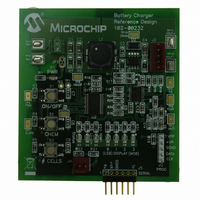
MCP1631RD-MCC2 Microchip Technology, MCP1631RD-MCC2 Datasheet - Page 150

MCP1631RD-MCC2
Manufacturer Part Number
MCP1631RD-MCC2
Description
REFERENCE DESIGN MCP1631HV
Manufacturer
Microchip Technology
Datasheets
1.MCP1631VHVT-330EST.pdf
(34 pages)
2.MCP1631HV-330EST.pdf
(54 pages)
3.MCP1631RD-MCC2.pdf
(20 pages)
4.MCP1631RD-MCC2.pdf
(328 pages)
Specifications of MCP1631RD-MCC2
Main Purpose
Power Management, Battery Charger
Embedded
Yes, MCU, 8-Bit
Utilized Ic / Part
MCP1631HV, PIC16F883
Primary Attributes
1 ~ 2 Cell- Li-Ion, 1 ~ 5 Cell- NiCd/NiMH, 1 ~ 2 1W LEDs
Secondary Attributes
Status LEDs
Silicon Manufacturer
Microchip
Application Sub Type
Battery Charger
Kit Application Type
Power Management - Battery
Silicon Core Number
MCP1631HV, PIC16F883
Kit Contents
Board
Lead Free Status / RoHS Status
Lead free / RoHS Compliant
Lead Free Status / RoHS Status
Lead free / RoHS Compliant
- MCP1631VHVT-330EST PDF datasheet
- MCP1631HV-330EST PDF datasheet #2
- MCP1631RD-MCC2 PDF datasheet #3
- MCP1631RD-MCC2 PDF datasheet #4
- Current page: 150 of 328
- Download datasheet (6Mb)
PIC16F882/883/884/886/887
11.6.7.1
The STRSYNC bit of the PSTRCON register gives the
user two selections of when the steering event will
happen. When the STRSYNC bit is ‘0’, the steering
event will happen at the end of the instruction that
writes to the PSTRCON register. In this case, the
output signal at the P1<D:A> pins may be an
incomplete PWM waveform. This operation is useful
when the user firmware needs to immediately remove
a PWM signal from the pin.
When the STRSYNC bit is ‘1’, the effective steering
update will happen at the beginning of the next PWM
period. In this case, steering on/off the PWM output will
always produce a complete PWM waveform.
FIGURE 11-20:
FIGURE 11-21:
DS41291F-page 148
P1<D:A>
P1<D:A>
STRn
PWM
STRn
PWM
Steering Synchronization
PORT Data
EXAMPLE OF STEERING EVENT AT END OF INSTRUCTION (STRSYNC = 0)
EXAMPLE OF STEERING EVENT AT BEGINNING OF INSTRUCTION
(STRSYNC = 1)
PWM Period
PORT Data
P1n = PWM
Figures 11-20 and 11-21 illustrate the timing diagrams
of the PWM steering depending on the STRSYNC
setting.
P1n = PWM
PORT Data
© 2009 Microchip Technology Inc.
PORT Data
Related parts for MCP1631RD-MCC2
Image
Part Number
Description
Manufacturer
Datasheet
Request
R

Part Number:
Description:
REFERENCE DESIGN FOR MCP1631HV
Manufacturer:
Microchip Technology
Datasheet:

Part Number:
Description:
REF DES BATT CHARG OR LED DRIVER
Manufacturer:
Microchip Technology
Datasheet:

Part Number:
Description:
Manufacturer:
Microchip Technology Inc.
Datasheet:

Part Number:
Description:
Manufacturer:
Microchip Technology Inc.
Datasheet:

Part Number:
Description:
Manufacturer:
Microchip Technology Inc.
Datasheet:

Part Number:
Description:
Manufacturer:
Microchip Technology Inc.
Datasheet:

Part Number:
Description:
Manufacturer:
Microchip Technology Inc.
Datasheet:

Part Number:
Description:
Manufacturer:
Microchip Technology Inc.
Datasheet:

Part Number:
Description:
Manufacturer:
Microchip Technology Inc.
Datasheet:

Part Number:
Description:
Manufacturer:
Microchip Technology Inc.
Datasheet:


