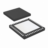
LM96194CISQ/NOPB National Semiconductor, LM96194CISQ/NOPB Datasheet - Page 72

LM96194CISQ/NOPB
Manufacturer Part Number
LM96194CISQ/NOPB
Description
IC TRUTHERM HDWR MONITOR 48-LLP
Manufacturer
National Semiconductor
Series
PowerWise®, TruTherm®r
Datasheet
1.LM96194CISQNOPB.pdf
(106 pages)
Specifications of LM96194CISQ/NOPB
Function
Fan Control, Temp Monitor
Topology
ADC (Sigma Delta), Comparator, Fan Control, Multiplexer, Register Bank
Sensor Type
External & Internal
Sensing Temperature
-40°C ~ 85°C, External Sensor
Output Type
SMBus™
Output Alarm
No
Output Fan
Yes
Voltage - Supply
3 V ~ 3.6 V
Operating Temperature
-40°C ~ 85°C
Mounting Type
Surface Mount
Package / Case
48-LLP
Lead Free Status / RoHS Status
Lead free / RoHS Compliant
Other names
LM96194CISQTR
www.national.com
Register
Address
16.13.2 Register BDh Special Function Control 2 (Smart Tach Mode Enable, Fan Control Temperature Resolution Control
and VID Mode Select)
Application Note: Enabling Smart Tach mode is not supported while either PWM output is configured for 22.5 kHz. The behavior
of the part is undefined if this configuration is programmed. Register E0h Special Function TACH to PWM Binding must be setup
when Smart Tach modes are enabled.
BDh
VID_MODE[1:0]
00
01
10
11
Read/
Write
R/W
7:6
Bit
0
1
2
3
4
5
7
Special Function
Register
Control 2
VID_MODE
VRD10.2 Extended
Name
LT12_RS
LT34_RS
VRD11 Mode 1
VRD11 Mode 2
Name
STE1
STE2
STE3
STE4
RES
[1:0]
VID Mode
VRD10
R/W
R/W
R/W
R/W
R/W
R/W
R/W
R/W
Bit 7
VID_MODE[1:0]
VID Mode Select Bit Description
R
Comments
Supports the VRD10 specification from Intel and is backwards compatible
with the LM93 dynamic Vccp monitoring circuitry. This mode has a voltage
range of 0.8375V to 1.600V with 12.5mV resolution and supports 6 VID bits/
pins.
Supports the VRD10.2 Extended specification from Intel. This mode has a
voltage range of 0.83125V to 1.600V with 6.25mV resolution and supports
7 VID bits/pins.
Supports the VRD11 specification from Intel. This mode has a voltage range
of 0.83125V to 1.600V with 6.25mV resolution and supports 7 VID bits/pins
(VID6-VID0). It assumes VID7 is 0. This is the recommended mode of
operation for support of VRD10 and VRD11 without requiring additional
hardware.
Supports the VRD11 specification from Intel. This mode has a voltage range
of 0.0375V to 1.600V with 12.5mV resolution and supports 7 VID bits/pins
(VID7-VID1). It assumes VID0 is 0. This mode measures voltage levels
below 0.83125V for VRD11, but will require additional hardware to
simultaneously support VRD10 operation.
Enable Smart Tach for Tach 1
Enable Smart Tach for Tach 2
Enable Smart Tach for Tach 3
Enable Smart Tach for Tach 4
When this bit is set, the LUT1 and LUT2 fan controls will
use 0.5°C. The resolution of the LUT offsets and
hysteresis settings are affected by this bit. These bits
apply to the fan control offset registers, fan control
hysteresis registers, and boost hysteresis registers.
When this bit is set, the LUT3 and LUT4 fan controls will
use 0.5°C. The resolution of the LUT offsets and
hysteresis settings are affected by this bit.
These bits select the VID mode which determines how
the VID code is handled by the VID value registers and
the dynamic Vccp monitoring.
Reserved
Bit 6
72
LT34
Bit 5
_RS
Description
Bit 4
LT12
_RS
STE4
Bit 3
STE3
Bit 2
STE2
Bit 1
STE1
Bit 0
Default
Value
00h


