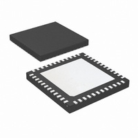
LM96194CISQ/NOPB National Semiconductor, LM96194CISQ/NOPB Datasheet - Page 11

LM96194CISQ/NOPB
Manufacturer Part Number
LM96194CISQ/NOPB
Description
IC TRUTHERM HDWR MONITOR 48-LLP
Manufacturer
National Semiconductor
Series
PowerWise®, TruTherm®r
Datasheet
1.LM96194CISQNOPB.pdf
(106 pages)
Specifications of LM96194CISQ/NOPB
Function
Fan Control, Temp Monitor
Topology
ADC (Sigma Delta), Comparator, Fan Control, Multiplexer, Register Bank
Sensor Type
External & Internal
Sensing Temperature
-40°C ~ 85°C, External Sensor
Output Type
SMBus™
Output Alarm
No
Output Fan
Yes
Voltage - Supply
3 V ~ 3.6 V
Operating Temperature
-40°C ~ 85°C
Mounting Type
Surface Mount
Package / Case
48-LLP
Lead Free Status / RoHS Status
Lead free / RoHS Compliant
Other names
LM96194CISQTR
12.3.1 “Remote Diode” TruTherm Mode
The processor “remote thermal diode” is more correctly de-
scribed as a transistor. The LM93 treated the “remote diode”
as a diode thus introducing inaccuracies. These inaccuracies
have become more apparent as the geometry of processors
is shrinking. The LM96194 can sense the “remote diode” us-
ing a new TruTherm technology that treats the remote device
as a transistor. The TruTherm Mode is more accurate for pro-
cessors on 90nm and smaller geometry. The LM96194 still
supports the old diode method and is callibrated for 2N3904
transistor type.
12.3.2 Temperature Data Format
Most of the temperature data for the LM96194 is represented
in three formats:
•
Note: A value of 80h has a special meaning in the limit registers. It means
that the temperature channel is masked. In addition, temperature readings
of 80h indicate thermal diode faults.
•
Zone 1a
Zone 1b
Zone 2a
Zone 2b
Zone 3
Zone 4
Temperature
+125.5°C
Zone
8-bit, two's complement byte with the LSb equal to 1.0 °C;
this applies to temperature measurements as well as any
temperature limit registers and some configuration
registers.
9–bit two's complement word with the LSb equal to 0.5°C;
this applies to unfiltered temperature measurement
extended resolution value registers
+25.5°C
−25.5°C
+0.5°C
−0.5°C
0°C
Temperature
+125°C
−127°C
+1.0°C
−1.0°C
+25°C
−25°C
−55°C
0°C
Processor 1 remote diode 1
(REMOTE1a+, REMOTE1−)
Processor 1 remote diode 2
(REMOTE1b+, REMOTE1–)
MMBT3904 remote diode 1
(REMOTE2a+, REMOTE2−)
MMBT2904 remote diode 2
(REMOTE2b+, REMOTE2–)
Internal LM96194 on-chip sensor; also accepts
writes via SMBus
External digital temperature value from SMBus
write to register 53h or external LM60 analog
sensor connected to AD_IN8
0111 1101
0001 1001
0000 0000
0000 0000
1111 1111
1110 0111
MSB
Binary
Description
1000 0000
1000 0000
1000 0000
0000 0000
1000 0000
1000 0000
0111 1101
0001 1001
0000 0001
0000 0000
1111 1111
1110 0111
1100 1001
1000 0001
LSB
Binary
7D 80h
19 80h
00 80h
00 00h
FF 80h
E7 80h
Hex
Hex
7Dh
C9h
19h
01h
00h
FFh
E7h
81h
11
•
Some fan control configuration registers use four bits and
have an unsigned binary format, please see the fan control
configuration register descriptions for further details on this 4-
bit format.
12.3.3 Thermal Diode Fault Status
The LM96194 provides for indications of a fault (open or short
circuit) with the remote thermal diodes. Before a remote diode
conversion is updated, the status of the remote diode is
checked for an open or short circuit condition. If such a fault
condition occurs, a status bit is set in the status register. A
short circuit is defined as the diode pins connected to each
other. When an open or short circuit is detected, the corre-
sponding temperature register is set to 80h.
12.4 EVENT ERRORS FOR FAN BOOST
Temperature boost error and tachometer error events can
cause the fan control PWM output(s) to go to full on. A boost
temperature error event will cause both PWM outputs to go
to full on, while a tachometer event can be either bound to
PWM1 or PWM2.
A fan boost temperature event occurs if any of the four tem-
perature zones exceeds the temperature Fan Boost Limit for
that zone. Once a temperature has exceed the boost limit, it
must drop to a value equal to the boost limit minus the boost
hysteresis before the boost condition is deactivated. The de-
fault setting for Zones 1 and 2 is 60°C and for Zones 3 and 4
it is 35°C.
The tachometer error boost function is enabled via the
Tachometer Fan Boost Control register. Depending on the
setting of the tachometer to PWM binding bits one or both of
the PWM outputs will go to 100% duty cycle upon the detec-
tion of an unmasked Fan Tachometer Error Event. A Fan
Tachometer Error event occurs when a tachometer reading
exceeds the value set in it's FAN Tach Limit register. Once
the error event ends the PWM output(s) will remain at 100%
duty cycled for a time interval, Tach Boost Timeout, as pro-
grammed in the Tachometer Fan Boost Control register. If the
tachometer error event returns during the middle of the timout
interval the Tach Boost Timeout interval will be reset and
restart once the error event ends.
12.5 VOLTAGE MONITORING
The LM96194 contains inputs for monitoring voltages. Scal-
ing is such that the correct value refers to approximately 3/4
Temperature
Temperature
+125.0625°C
−127.0625°C
+25.0625°C
−25.0625°C
−55.0625°C
+1.0625°C
−0.0625°C
−127.5°C
12–bit two's complement word with the LSb equal to
0.0625°C; this applies to extended filtered temperature
measurement extended resolution value registers
−55.5°C
0°C
1100 1001
1000 0001
0111 1101
0001 1001
0000 0001
0000 0000
1111 1111
1110 0111
1100 1001
1000 0000
MSB
MSB
Binary
Binary
1000 0000
1000 0000
0001 0000
0001 0000
0001 0000
0000 0000
1111 0000
1111 0000
1111 0000
1111 0000
LSB
LSB
www.national.com
C9 80h
7D 10h
FF F0h
E7 F0h
C9 F0h
81 80h
19 10h
01 10h
00 00h
80 F0h
Hex
Hex


