DS3170+ Maxim Integrated Products, DS3170+ Datasheet - Page 77
DS3170+
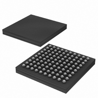
Manufacturer Part Number
DS3170+
Description
IC TXRX DS3/E3 100-CSBGA
Manufacturer
Maxim Integrated Products
Datasheet
1.DS3170.pdf
(230 pages)
Specifications of DS3170+
Function
Single-Chip Transceiver
Interface
DS3, E3
Number Of Circuits
1
Voltage - Supply
3.135 V ~ 3.465 V
Current - Supply
120mA
Operating Temperature
0°C ~ 70°C
Mounting Type
Surface Mount
Package / Case
100-LBGA
Includes
DS3 Framers, E3 Framers, HDLC Controller, On-Chip BERTs
Lead Free Status / RoHS Status
Lead free / RoHS Compliant
Power (watts)
-


Table 10-23. RSOFO/RDEN Output Pin Functions
Table 10-24. RCLKO/RGCLK Output Pin Functions
10.5.9 Framing Modes
The framing modes are selected independently of the line interface modes using the PORT.CR2.FM[2:0] control
bits. Different blocks are used in different framing modes. The bit error test (BERT) function can be enabled in any
mode. The LIU, JA and line encoder/decoder blocks are selected by the line mode (LM[2:0]) code.
Table 10-25. Framing Mode Select Bits FM[2:0]
10.5.10 Line Interface Modes
The line interface modes can be selected semi-independently of the framing modes using the PORT.CR2.LM[2:0]
control bits. The major blocks controlled are the transmit LIU (Tx LIU), receive LIU (RX LIU), jitter attenuator (JA)
and the line encoder/decoder. The line encoder/decoder is used for B3ZS, HDB3 and AMI line interface encoding
modes. The line encoder-decoder block is not used for line encoding or decoding in the UNI mode but the BPV
counter in it can be used to count external pulses on the RNEG / RCLV pin. The jitter attenuator (JA) can be off
(OFF) or put in either the transmit (Tx) or receive (RX) path with the Tx LIU or RX LIU. Both Tx LIU and RX LIU can
be enabled (ON) or disabled (OFF).
The “Analog Loop Back” (ALB) is available when the LIU is enabled or disabled. It is an actual loop back of the
analog positive and negative pulses from the TX LIU to the RX LIU when the LIU is enabled. If the LIU is disabled,
It is a digital loop back of the TLCLK, TPOS, TNEG signals to the RLCLK, RPOS and RNEG signals.
When the line is configured for B3ZS/HDB3/AMI line codes, the line codes are determined by the framing mode
and the AMI line mode selection is controlled by the TZCDS and RZCDS bits in the line encoder/decoder blocks.
The DS3 modes select the B3ZS line coding, the E3 modes select the HDB3 line codes. Refer to
configuration.
FM[2:0]
1XX (UFRM)
1XX (UFRM)
PORT.CR2
PORT.CR2
0XX (FRM)
0XX (FRM)
0XX (FRM)
0XX (FRM)
0 00
0 01
0 10
0 11
1 00
1 01
1 10
1 11
FM[2:0]
FM[2:0]
DS3 C-bit Framed
DS3 M23 Framed
E3 G.751 Famed
E3 G.832 Framed
DS3 Unframed
Undefined
E3 Unframed
Undefined
PORT.CR3
PORT.CR3
RSOFOS
RCLKS
DESCRIPTION
X
0
1
X
0
1
FUNCTION
FUNCTION
RSOFO
RGCLK
RCLKO
RCLKO
RDEN
High
PIN
PIN
77 of 230
GAP SOURCE
B3ZS/AMI/UNI
B3ZS/AMI/UNI
HDB3/AMI/UNI
HDB3/AMI/UNI
B3ZS/AMI/UNI
---
HDB3/AMI/UNI
---
LINE CODE
RDEN
none
none
DS3170 DS3/E3 Single-Chip Transceiver
Figure 7-1
Figure 7-1
Figure 7-1
Figure 7-1
Figure 7-2
Figure 7-2
FIGURE
Table 10-26
for
Related parts for DS3170+
Image
Part Number
Description
Manufacturer
Datasheet
Request
R

Part Number:
Description:
MAX7528KCWPMaxim Integrated Products [CMOS Dual 8-Bit Buffered Multiplying DACs]
Manufacturer:
Maxim Integrated Products
Datasheet:
Part Number:
Description:
Single +5V, fully integrated, 1.25Gbps laser diode driver.
Manufacturer:
Maxim Integrated Products
Datasheet:
Part Number:
Description:
Single +5V, fully integrated, 155Mbps laser diode driver.
Manufacturer:
Maxim Integrated Products
Datasheet:
Part Number:
Description:
VRD11/VRD10, K8 Rev F 2/3/4-Phase PWM Controllers with Integrated Dual MOSFET Drivers
Manufacturer:
Maxim Integrated Products
Datasheet:
Part Number:
Description:
Highly Integrated Level 2 SMBus Battery Chargers
Manufacturer:
Maxim Integrated Products
Datasheet:
Part Number:
Description:
Current Monitor and Accumulator with Integrated Sense Resistor; ; Temperature Range: -40°C to +85°C
Manufacturer:
Maxim Integrated Products
Part Number:
Description:
TSSOP 14/A�/RS-485 Transceivers with Integrated 100O/120O Termination Resis
Manufacturer:
Maxim Integrated Products
Part Number:
Description:
TSSOP 14/A�/RS-485 Transceivers with Integrated 100O/120O Termination Resis
Manufacturer:
Maxim Integrated Products
Part Number:
Description:
QFN 16/A�/AC-DC and DC-DC Peak-Current-Mode Converters with Integrated Step
Manufacturer:
Maxim Integrated Products
Part Number:
Description:
TDFN/A/65V, 1A, 600KHZ, SYNCHRONOUS STEP-DOWN REGULATOR WITH INTEGRATED SWI
Manufacturer:
Maxim Integrated Products
Part Number:
Description:
Integrated Temperature Controller f
Manufacturer:
Maxim Integrated Products
Part Number:
Description:
SOT23-6/I�/45MHz to 650MHz, Integrated IF VCOs with Differential Output
Manufacturer:
Maxim Integrated Products
Part Number:
Description:
SOT23-6/I�/45MHz to 650MHz, Integrated IF VCOs with Differential Output
Manufacturer:
Maxim Integrated Products
Part Number:
Description:
EVALUATION KIT/2.4GHZ TO 2.5GHZ 802.11G/B RF TRANSCEIVER WITH INTEGRATED PA
Manufacturer:
Maxim Integrated Products
Part Number:
Description:
QFN/E/DUAL PCIE/SATA HIGH SPEED SWITCH WITH INTEGRATED BIAS RESISTOR
Manufacturer:
Maxim Integrated Products
Datasheet: