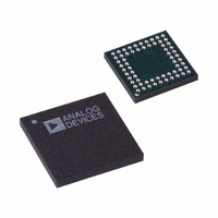
AD9929BBCZ Analog Devices Inc, AD9929BBCZ Datasheet - Page 27

AD9929BBCZ
Manufacturer Part Number
AD9929BBCZ
Description
IC CCD SIGNAL PROCESSOR 64-BGA
Manufacturer
Analog Devices Inc
Type
CCD Signal Processor, 12-Bitr
Datasheet
1.AD9929BBCZ.pdf
(64 pages)
Specifications of AD9929BBCZ
Input Type
Logic
Output Type
Logic
Interface
3-Wire Serial
Mounting Type
Surface Mount
Package / Case
64-CSPBGA
Analog Front End Type
CCD
Analog Front End Category
Video
Interface Type
Serial (3-Wire)
Input Voltage Range
0.5V
Operating Supply Voltage (min)
2.7V
Operating Supply Voltage (typ)
3V
Operating Supply Voltage (max)
3.6V
Resolution
12b
Number Of Adc's
1
Power Supply Type
Analog/Digital
Operating Temp Range
-20C to 85C
Operating Temperature Classification
Commercial
Mounting
Surface Mount
Pin Count
64
Package Type
CSPBGA
Number Of Channels
1
Lead Free Status / RoHS Status
Lead free / RoHS Compliant
Current - Supply
-
Lead Free Status / RoHS Status
Compliant, Lead free / RoHS Compliant
Available stocks
Company
Part Number
Manufacturer
Quantity
Price
Company:
Part Number:
AD9929BBCZ
Manufacturer:
ADI
Quantity:
531
EXTERNAL SYNCHRONIZATION (MASTER MODE)
External synchronization can be applied to synchronize the VD
and HD signals by applying an external pulse on the
SYNC/GATE (Pin 45) pin for master mode operation. The
SYNC/GATE pin is configured as an external SYNC input for
master mode operation by setting the SLAVE_MODE register
(Address 0xD6) = 0 (the AD9929 defaults to slave mode at
power-up).
SYNCCNT (Address 0x0A) and SYNCPOL (Address 0x01) are
the only two registers used for configuring the AD9929 for
external synchronization. The SYNCPOL is a 1-bit register used
for configuring the SYNC input as either active low or active
high. The AD9929 defaults to active low at power-up. The
function of the SYNCCNT register is described in Table 17.
Figure 20 and Figure 21 provide two examples of external
synchronization with SYNCPOL = 0.
OPERATION
SYNC
WRITES
SERIAL
MODE
SYNC
VD
VD
Figure 20. Example of Synchronization with SYNCPOL = 0 and SYNCCNT = 1
Figure 21. Example of Synchronization with SYNCPOL = 0 and CYNCCNT = 3
2 CLI
2 CLI
4 CLI
MIN
4 CLI
MIN
MODE A
Rev. A | Page 27 of 64
4 CLI
4 CLI
Table 17. External Synchronization (Master Mode)
SYNCCNT
0
1
2
3
4
5
6
7
8
9
10
11
12
13
14
15
CHANGE TO MODE B
External Synchronization Options
Disable External Synchronization
VD Sync at every SYNC Pulse
VD Sync after 2nd Applied SYNC Pulse
VD Sync after 3rd Applied SYNC Pulse
VD Sync after 4th Applied SYNC Pulse
VD Sync after 5th Applied SYNC Pulse
VD Sync after 6th Applied SYNC Pulse
VD Sync after 7th Applied SYNC Pulse
VD Sync after 8th Applied SYNC Pulse
VD Sync after 9th Applied SYNC Pulse
VD Sync after 10th Applied SYNC Pulse
VD Sync after 11th Applied SYNC Pulse
VD Sync after 12th Applied SYNC Pulse
VD Sync after 13th Applied SYNC Pulse
VD Sync after 14th Applied SYNC Pulse
VD Sync after 1st Applied SYNC Pulse Only
4 CLI
4 CLI
MODE B
AD9929


