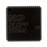
ISP1583BSUM ST-Ericsson Inc, ISP1583BSUM Datasheet - Page 34

ISP1583BSUM
Manufacturer Part Number
ISP1583BSUM
Description
IC USB PERIPH CONTROLLER 64HVQFN
Manufacturer
ST-Ericsson Inc
Datasheet
1.ISP1583BSUM.pdf
(100 pages)
Specifications of ISP1583BSUM
Controller Type
USB Peripheral Controller
Interface
Parallel/Serial
Voltage - Supply
3 V ~ 3.6 V
Current - Supply
47mA
Operating Temperature
-40°C ~ 85°C
Mounting Type
Surface Mount
Package / Case
64-VQFN Exposed Pad, 64-HVQFN, 64-SQFN, 64-DHVQFN
Lead Free Status / RoHS Status
Lead free / RoHS Compliant
Other names
568-1886-2
ISP1583BS,518
ISP1583BS-T
ISP1583BS,518
ISP1583BS-T
Available stocks
Company
Part Number
Manufacturer
Quantity
Price
Company:
Part Number:
ISP1583BSUM
Manufacturer:
MICRON
Quantity:
2 000
Company:
Part Number:
ISP1583BSUM
Manufacturer:
ST-ERICS
Quantity:
829
Part Number:
ISP1583BSUM
Manufacturer:
STE
Quantity:
20 000
NXP Semiconductors
ISP1583_7
Product data sheet
9.2.3 Interrupt Configuration register (address: 10h)
Table 25.
The status of the chip is shown in
Table 26.
This 1-byte register determines the behavior and polarity of the INT output. The bit
allocation is shown in
NYET, it will generate interrupts, depending on three Debug mode fields.
CDBGMOD[1:0] — interrupts for control endpoint 0
DDBGMODIN[1:0] — interrupts for DATA IN endpoints 1 to 7
DDBGMODOUT[1:0] — interrupts for DATA OUT endpoints 1 to 7
The Debug mode settings for CDBGMOD, DDBGMODIN and DDBGMODOUT allow you
to individually configure when the ISP1583 sends an interrupt to the external
microprocessor.
Bit INTPOL controls the signal polarity of the INT output: active HIGH or LOW, rising or
falling edge. For level-triggering, bit INTLVL must be made logic 0. By setting INTLVL to
logic 1, an interrupt will generate a pulse of 60 ns (edge-triggering).
Bit
3
2
1
0
Bus state
V
V
BUS
BUS
on
off
Symbol
GLINTENA
WKUPCS
PWRON
SOFTCT
Mode register: bit description
Status of the chip
SoftConnect = on
pull-up resistor on pin DP
pull-up resistor on pin DP is present;
suspend interrupt is generated after
3 ms of no bus activity
Table 29
Rev. 07 — 22 September 2008
Table
Description
Global Interrupt Enable: Logic 1 enables all interrupts. Individual
interrupts can be masked by clearing the corresponding bits in the
Interrupt Enable register.
When this bit is not set, an unmasked interrupt will not generate an
interrupt trigger on the interrupt pin. If global interrupt, however, is
enabled while there is any pending unmasked interrupt, an interrupt
signal will be immediately generated on the interrupt pin. (If the interrupt
is set to pulse mode, the interrupt events that were generated before the
global interrupt is enabled will not appear on the interrupt pin.)
Wake-up on Chip selection: Logic 1 enables wake-up from suspend
mode through a valid register read on the ISP1583. (A read will invoke
the chip clock to restart. If you write to the register before the clock gets
stable, it may cause malfunctioning.)
Power On: The SUSPEND pin output control.
0 — The SUSPEND pin is HIGH when the ISP1583 is in the suspend
state. Otherwise, the SUSPEND pin is LOW.
1 — When the device is woken up from the suspend state, there will be
a 1 ms active HIGH pulse on the SUSPEND pin. The SUSPEND pin will
remain LOW in all other states.
SoftConnect: Logic 1 enables the connection of the 1.5 k pull-up
resistor on pin RPU to the DP pin.
lists available combinations.
27. When the USB SIE receives or generates an ACK, NAK or
Table
…continued
26.
SoftConnect = off
pull-up resistor on pin DP is removed;
suspend interrupt is generated after 3 ms of
no bus activity
pull-up resistor on pin DP is removed;
suspend interrupt is generated after 3 ms of
no bus activity
Hi-Speed USB peripheral controller
© NXP B.V. 2008. All rights reserved.
ISP1583
33 of 99


