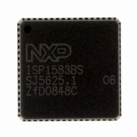
ISP1583BSUM ST-Ericsson Inc, ISP1583BSUM Datasheet - Page 11

ISP1583BSUM
Manufacturer Part Number
ISP1583BSUM
Description
IC USB PERIPH CONTROLLER 64HVQFN
Manufacturer
ST-Ericsson Inc
Datasheet
1.ISP1583BSUM.pdf
(100 pages)
Specifications of ISP1583BSUM
Controller Type
USB Peripheral Controller
Interface
Parallel/Serial
Voltage - Supply
3 V ~ 3.6 V
Current - Supply
47mA
Operating Temperature
-40°C ~ 85°C
Mounting Type
Surface Mount
Package / Case
64-VQFN Exposed Pad, 64-HVQFN, 64-SQFN, 64-DHVQFN
Lead Free Status / RoHS Status
Lead free / RoHS Compliant
Other names
568-1886-2
ISP1583BS,518
ISP1583BS-T
ISP1583BS,518
ISP1583BS-T
Available stocks
Company
Part Number
Manufacturer
Quantity
Price
Company:
Part Number:
ISP1583BSUM
Manufacturer:
MICRON
Quantity:
2 000
Company:
Part Number:
ISP1583BSUM
Manufacturer:
ST-ERICS
Quantity:
829
Part Number:
ISP1583BSUM
Manufacturer:
STE
Quantity:
20 000
NXP Semiconductors
Table 3.
ISP1583_7
Product data sheet
Symbol
DATA10
DATA11
DATA12
DATA13
DATA14
DATA15
V
V
VCC1V8
XTAL2
XTAL1
DGND
MODE0/
DA1
V
CC(I/O)
BUS
CC(3V3)
[3]
[4]
[1]
[4]
[4]
Pin description
Pin
48
49
50
51
52
53
54
55
56
57
58
59
60
61
ISP1583BS ISP1583ET;
ISP1583ET2
A10
A9
B8
A8
B7
A7
B6
B5
A6
A5
A4
B4
A3
B3
…continued
ISP1583ET1
A8
C4
B7
A7
C6
C5
B6
A6
B5
A5
A4
B4
C2
B3
Rev. 07 — 22 September 2008
Type
I/O
I/O
I/O
I/O
I/O
I/O
-
A
-
O
I
-
I/O
-
[2]
Description
bit 10 of the bidirectional data bus
bidirectional pad; 4 ns slew-rate control; TTL; 5 V tolerant
bit 11 of the bidirectional data bus
bidirectional pad; 4 ns slew-rate control; TTL; 5 V tolerant
bit 12 of the bidirectional data bus
bidirectional pad; 4 ns slew-rate control; TTL; 5 V tolerant
bit 13 of the bidirectional data bus
bidirectional pad; 4 ns slew-rate control; TTL; 5 V tolerant
bit 14 of the bidirectional data bus
bidirectional pad; 4 ns slew-rate control; TTL; 5 V tolerant
bit 15 of the bidirectional data bus
bidirectional pad; 4 ns slew-rate control; TTL; 5 V tolerant
I/O pad supply voltage (1.65 V to 3.6 V); see
USB bus power sensing input — Used to detect
whether the host is connected or not; connect a 1 F
electrolytic or tantalum capacitor and a 1 M pull-down
resistor to ground; see
V
electrolytic or tantalum capacitor and a 1 M pull-down
resistor to ground; see
5 V tolerant
voltage regulator output (1.8 V
voltage from the internal regulator; this regulated voltage
cannot drive external devices; decouple this pin using
4.7 F and 0.1 F capacitors; see
crystal oscillator output (12 MHz); connect a fundamental
parallel-resonant crystal; leave this pin open when using
an external clock source on pin XTAL1; see
crystal oscillator input (12 MHz); connect a fundamental
parallel-resonant crystal or an external clock source
(leaving pin XTAL2 unconnected); see
digital ground
Mode selection input 0 — Selects the read/write strobe
functionality in generic processor mode during power-up:
Address selection output — Selects the Task File
register of an ATA/ATAPI device during normal operation;
see
bidirectional pad; 10 ns slew-rate control; TTL; 5 V tolerant
regulator supply voltage (3.3 V
the internal regulator; see
BUS
•
•
Table 61
LOW: for the Freescale mode; the function of pin 19 is
RW_N and pin 20 is DS_N
HIGH (connect to V
function of pin 19 is RD_N and pin 20 is WR_N
pulsing output — In OTG mode; connect a 1 F
Hi-Speed USB peripheral controller
Section 8.14
Section 8.14
CC(I/O)
Section 8.16
): for the 8051 mode; the
0.15 V); tapped out
0.3 V); this pin supplies
Section 8.16
Table 100
© NXP B.V. 2008. All rights reserved.
ISP1583
Table 100
Section 8.16
10 of 99


